• Em Destaque

    Aqui Você Encontra Os Melhores Template da Internet .

  • Em Destaque

    Aqui Você Encontra Os Melhores Template da Internet .

  • Em Destaque

    Aqui Você Encontra Os Melhores Template da Internet .

  • Em Destaque

    Aqui Você Encontra Os Melhores Template da Internet .

  • Curte aí!

    Tuesday, 31 January 2012

    Name of the Experiment: 
    Determination of fabric crease recovery by Shirley Crease Recovery Tester.

    Introduction:
    Crease is a fold in fabric introduced unintentionally at some stages of processing. Crease or crushing of textile material is a complex effect involving tensile, compressive, flexing and torsional stresses. Crease recovery is a fabric property which indicates the ability of fabric to go back to its original position after creasing.


    Objective:
    To measure the crease recovery of the given fabric.

    Theory:
    Crease recovery is a measure of creases resistance, specified quantitatively in terms of crease recovery angle. To measure this, the popular instrument is Shirley crease recovery tester. The instrument consists of a circular dial which carries the clamp for holding the specimen. Directly under the centre of the dial there is a knife edge and an index line for measuring the recovery angle. Crease recovery is determined depending upon this recovery angle. If the angle is 0o then recovery is zero and if the angle is 180o then recovery is full. Crease recovery depends on the construction, twist of yarn, pressure, time etc. Usually crease recovery is more in warp way than in weft way. This is because warp yarns are well in quality, strength, treated with sizing, kept in more tension during weaving etc.

    Crease Recovery Tester
    Apparatus:  
    1. Crease recovery tester
    2. Scissor
    3. Glass plates
    4. Steel plates
    5. Weight.
    Sample:  
    • Cotton woven fabric.
    • Size: 4.4 X 1.5cm.
    Atmosphere:  
    • Temperature – 25oC and relative humidity – 67%
    • Standard atmosphere: temperature – 20oC and relative humidity - 65%.
    M/c specification:  
    • Name: Wrinkle Recovery Tester
    • Brand: TAIEI KAGAKU FEIKI Ltd., Japan
    • Scale: 0o-180o.
    Procedure:
    1. The specimen is cut by template and carefully creased by folding in half.
    2. The crease is imparted on fabric by placing it between two glass plates and adding to 500gm weight on it.
    3. After 1 min the weight is removed and the creased fabric is clamped on the instrument.
    4. Then it is allowed to recover from the crease. The recovery time may vary to suit particular creases. Usually it is 1 min.
    5. When crease recovers the dial of the instrument is rotated to keep the free edge of the specimen inline with the knife edge.
    6. The recovery angle is read from the engraved scale.
    7. In this way 10 tests are done in warp way and 10 for weft way.
    8. The mean value of recovery angle is taken and thus crease recovery is measured.
    Data:

    S/n
    Warp
    Weft
    Recovery angle
    Average
    Recovery angle
    Average
    1
    70o
    57.4o
    41o
    41.8o
    2
    40o
    39o
    3
    52o
    44o
    4
    60o
    37o
    5
    65o
    48o
    Table: Recovery angle obtained from test
    Result:  
    1. Crease recovery angle in warp way is 57.4o.
    2. Crease recovery angle in weft way is 41.8o.
    Remark:
    Crease recovery is determined depending upon the recovery angle. If the angle is 0o then recovery is zero and if the angle is 180o then recovery is full. Here the recovery angle for the given fabric sample is the middle of the range. So it is to say that the crease recovery of the sample fabric is average.

    Determination of Fabric Crease Recovery by Shirley Crease RecoveryTester

    Posted at  02:17  |  in  Testing M/C  |  Continue lendo ...»

    Name of the Experiment: 
    Determination of fabric crease recovery by Shirley Crease Recovery Tester.

    Introduction:
    Crease is a fold in fabric introduced unintentionally at some stages of processing. Crease or crushing of textile material is a complex effect involving tensile, compressive, flexing and torsional stresses. Crease recovery is a fabric property which indicates the ability of fabric to go back to its original position after creasing.


    Objective:
    To measure the crease recovery of the given fabric.

    Theory:
    Crease recovery is a measure of creases resistance, specified quantitatively in terms of crease recovery angle. To measure this, the popular instrument is Shirley crease recovery tester. The instrument consists of a circular dial which carries the clamp for holding the specimen. Directly under the centre of the dial there is a knife edge and an index line for measuring the recovery angle. Crease recovery is determined depending upon this recovery angle. If the angle is 0o then recovery is zero and if the angle is 180o then recovery is full. Crease recovery depends on the construction, twist of yarn, pressure, time etc. Usually crease recovery is more in warp way than in weft way. This is because warp yarns are well in quality, strength, treated with sizing, kept in more tension during weaving etc.

    Crease Recovery Tester
    Apparatus:  
    1. Crease recovery tester
    2. Scissor
    3. Glass plates
    4. Steel plates
    5. Weight.
    Sample:  
    • Cotton woven fabric.
    • Size: 4.4 X 1.5cm.
    Atmosphere:  
    • Temperature – 25oC and relative humidity – 67%
    • Standard atmosphere: temperature – 20oC and relative humidity - 65%.
    M/c specification:  
    • Name: Wrinkle Recovery Tester
    • Brand: TAIEI KAGAKU FEIKI Ltd., Japan
    • Scale: 0o-180o.
    Procedure:
    1. The specimen is cut by template and carefully creased by folding in half.
    2. The crease is imparted on fabric by placing it between two glass plates and adding to 500gm weight on it.
    3. After 1 min the weight is removed and the creased fabric is clamped on the instrument.
    4. Then it is allowed to recover from the crease. The recovery time may vary to suit particular creases. Usually it is 1 min.
    5. When crease recovers the dial of the instrument is rotated to keep the free edge of the specimen inline with the knife edge.
    6. The recovery angle is read from the engraved scale.
    7. In this way 10 tests are done in warp way and 10 for weft way.
    8. The mean value of recovery angle is taken and thus crease recovery is measured.
    Data:

    S/n
    Warp
    Weft
    Recovery angle
    Average
    Recovery angle
    Average
    1
    70o
    57.4o
    41o
    41.8o
    2
    40o
    39o
    3
    52o
    44o
    4
    60o
    37o
    5
    65o
    48o
    Table: Recovery angle obtained from test
    Result:  
    1. Crease recovery angle in warp way is 57.4o.
    2. Crease recovery angle in weft way is 41.8o.
    Remark:
    Crease recovery is determined depending upon the recovery angle. If the angle is 0o then recovery is zero and if the angle is 180o then recovery is full. Here the recovery angle for the given fabric sample is the middle of the range. So it is to say that the crease recovery of the sample fabric is average.

    Name of the Experiment: Determination of carpet thickness by Shirley thickness tester.

    Introduction:
    Carpet is a floor-covering textile having surface formed from yarns or fibres projecting from a substrate. Fabric thickness is a parameter of fabric which involves handle, creasing, wrinkle resistance, thermal resistance and other fabric properties. A carpet is compressible and therefore it is necessary to specify at what pressure its thickness is to be measured.

    Objective:
    To determine the thickness of carpet and understand its related facts.

    Theory:
    Anderson and Clegg state: Thickness as estimated by eye is similar to that measured by an instrument at low pressure, and by measuring thickness at increasing and decreasing pressures in the range exerted by a human foot, pressures of the order of 0-12 lb/in2 normally being encountered, we can obtain a measure of the behaviour of carpets to imposed loads. Essentially the determination of fabric thickness consists of the precise measurement of the distance between two plain parallel plates when they are separated by the cloth, a known arbitrary pressure between the plates being applied and maintained. It is convenient to regard one of the two plates as the pressure foot and the other as anvil. The Shirley thickness tester has such two parallel plates. The upper plate serves as a collar and supports for the additional load which produce pressure. The dial gauge is graduated in mm which indicates the thickness of the carpet.

    Apparatus:
    1. Shirley thickness tester
    2. Carpet
    3. Knife
    4. Scale.

    M/c specification:
    Name: Shirley thickness tester
    Manufacturer: Shirley Developments Limited, Manchester.

    Atmosphere:
    Testing atmosphere: Relative humidity - 65%+/-2% & Temperature - 270+/-20C.
    Present atmosphere: Relative humidity - 68% & Temperature - 290.

    Procedure:
    1. At first we will take our sample carpet and cuts it with a knife.
    2. Place the carpet on the lower plate and bring down the upper plate on it.
    3. Load the dead weight on the collar and takes the reading from the dial gauge.
    4. Now add the other additional weights one after another on the collar to increase the weight.
    5. And take the readings from the dial gauge.
    6. After taking the last reading we will wait for 5 mins for the action of the weights on the carpet.
    7. Then we will again unload the weights from the collar one by one and take the reading of the thickness.
    8. From the beginning thickness and the last thickness of the carpet after compression we will find out the compression of the carpet and the recovery percentage.

    Data:


    S/n
    Adding load (gm)
    Total load (gm)
    Thickness (mm) after loading
    Thickness (mm) after unloading
    1
    90 (dead wt.)
    90
    12.8
    12.5
    2
    200
    290
    12.7
    12.5
    3
    300
    590
    12.6
    12.5
    4
    500
    1090
    12.5
    12.4
    5
    1000
    2090
    12.4
    12.3
    6
    1000
    3090
    12.3
    12.2
    Calculation:
    Compression = (12.8 - 12.5) mm = 0.3 mm
    Recovery =  2.4%

    Result:
    Compression of the carpet = 0.3 mm and recovery = 2.4%.

    Graphical Representation:
    We can make a chart of loading and unloading on carpet thickness by placing the values of load or unload in Y axis and thickness in X axis. It is shown below: 


    Remark:
    The thickness of the carpet is compressed very little and so it may say that its load bearing capacity is good and its durability will be long. Again its recovery percentage is poor which indicates that if it is bended once it will not serves long which indicates that its service ability is poor.

    Carpet Thickness Tester | Working Principle of Shirley Carpet ThicknessTester

    Posted at  01:00  |  in  TTQC  |  Continue lendo ...»

    Name of the Experiment: Determination of carpet thickness by Shirley thickness tester.

    Introduction:
    Carpet is a floor-covering textile having surface formed from yarns or fibres projecting from a substrate. Fabric thickness is a parameter of fabric which involves handle, creasing, wrinkle resistance, thermal resistance and other fabric properties. A carpet is compressible and therefore it is necessary to specify at what pressure its thickness is to be measured.

    Objective:
    To determine the thickness of carpet and understand its related facts.

    Theory:
    Anderson and Clegg state: Thickness as estimated by eye is similar to that measured by an instrument at low pressure, and by measuring thickness at increasing and decreasing pressures in the range exerted by a human foot, pressures of the order of 0-12 lb/in2 normally being encountered, we can obtain a measure of the behaviour of carpets to imposed loads. Essentially the determination of fabric thickness consists of the precise measurement of the distance between two plain parallel plates when they are separated by the cloth, a known arbitrary pressure between the plates being applied and maintained. It is convenient to regard one of the two plates as the pressure foot and the other as anvil. The Shirley thickness tester has such two parallel plates. The upper plate serves as a collar and supports for the additional load which produce pressure. The dial gauge is graduated in mm which indicates the thickness of the carpet.

    Apparatus:
    1. Shirley thickness tester
    2. Carpet
    3. Knife
    4. Scale.

    M/c specification:
    Name: Shirley thickness tester
    Manufacturer: Shirley Developments Limited, Manchester.

    Atmosphere:
    Testing atmosphere: Relative humidity - 65%+/-2% & Temperature - 270+/-20C.
    Present atmosphere: Relative humidity - 68% & Temperature - 290.

    Procedure:
    1. At first we will take our sample carpet and cuts it with a knife.
    2. Place the carpet on the lower plate and bring down the upper plate on it.
    3. Load the dead weight on the collar and takes the reading from the dial gauge.
    4. Now add the other additional weights one after another on the collar to increase the weight.
    5. And take the readings from the dial gauge.
    6. After taking the last reading we will wait for 5 mins for the action of the weights on the carpet.
    7. Then we will again unload the weights from the collar one by one and take the reading of the thickness.
    8. From the beginning thickness and the last thickness of the carpet after compression we will find out the compression of the carpet and the recovery percentage.

    Data:


    S/n
    Adding load (gm)
    Total load (gm)
    Thickness (mm) after loading
    Thickness (mm) after unloading
    1
    90 (dead wt.)
    90
    12.8
    12.5
    2
    200
    290
    12.7
    12.5
    3
    300
    590
    12.6
    12.5
    4
    500
    1090
    12.5
    12.4
    5
    1000
    2090
    12.4
    12.3
    6
    1000
    3090
    12.3
    12.2
    Calculation:
    Compression = (12.8 - 12.5) mm = 0.3 mm
    Recovery =  2.4%

    Result:
    Compression of the carpet = 0.3 mm and recovery = 2.4%.

    Graphical Representation:
    We can make a chart of loading and unloading on carpet thickness by placing the values of load or unload in Y axis and thickness in X axis. It is shown below: 


    Remark:
    The thickness of the carpet is compressed very little and so it may say that its load bearing capacity is good and its durability will be long. Again its recovery percentage is poor which indicates that if it is bended once it will not serves long which indicates that its service ability is poor.

    Monday, 30 January 2012

    Name of the Experiment: Determination of fabric abrasion resistance by abrasion resistance tester.

    Introduction:
    Abrasion is just one aspect of wear and is the rubbing away of the component fibres and yarns of the fabric. It is a series of repeated applications of stress; therefore a capacity to absorb punishment is required to the fibres. Inherent fibre properties such as work of rupture may give a high resistance to abrasion.

    Objective:
    To determine the abrasion resistance of the sample fabric.

    Theory:
    A number of important points require consideration before abrasion resistance tests are carried out. The choice of the method may be governed by the type of apparatus available, the precision demanded and so forth. Some of the more important points are condition of the specimen, choice of testing instrument, choice of abrasive motion, direction of abrasion, choice of abradant, backing the specimen, cleanliness of the specimen and instrument, tension on the specimen, pressure between abradant and specimen, end-point of the test etc. Now there are various abrasion resistance testing instruments available for example, the WIRA abrasion tester, the LIRA abrasion tester, the Taber abraser, the Shiefer machine, the Wyzenbeek abrasion tester, the Stoll universal wear tester, the LINRA wear tester, the BFT abrasion tester etc. The abrasion tester we used here is made by GOODBRAND & CO. LTD. In this instrument abrasion surfaces wrapping by sand paper are used to abrade the fabric samples. A counter is used to count the no. of abrasion. This is an electrical tester.

    Apparatus:
    1. Abrasion tester
    2. Scissor
    3. Electric balance
    4. Brush

    M/c specification:

    Name: Abrasion Tester
    Manufacturer: GOODBRAND & CO. LTD.
    ELM WORKS, MERE LANE
    ROCHDALE, ENGLAND.
    Serial no.: GB 78627.
    Sample: Canvas fabric.

    Atmospheric status:
    Testing atmosphere: Relative humidity - 65%+/-2% & Temperature - 270+/-20C.
    Present atmosphere: Relative humidity - 68% & Temperature - 290.

    Procedure:
    1. At first cut the fabric into 4 pieces according to the measurement of the instrument.
    2. Weigh these 4 pieces of fabric samples.
    3. Now place these samples in the instrument under a certain load as supplied in the instrument.
    4. Now start the machine and observe the counter of abrasion no.
    5. After an abrasion of 200 bring out the first sample and weigh it.
    6. After an abrasion of 300 bring out the second sample and weigh it.
    7. Similarly after abrasion of 400 and 500 bring out the third and fourth sample and take their weight.
    8. Now put the weights before and after abrasions in a table and find out their wear index.

    Data:


    S/n
    Sample wt. before abrasion (mg)
    No. of abrasion cycle
    Sample wt. before abrasion (mg)
    Wt. loss
    Wear index
    1
    4970
    200
    4940
    30
    6
    2
    4680
    300
    4640
    40
    8
    3
    4860
    400
    4790
    70
    14
    4
    4870
    500
    4770
    170
    34
    Calculation:

    Suppose for s/n 2, we got cycle = 300, wt. loss = 40 therefore,


    Result:
    Wear index for 200 cycle = 6
    Wear index for 200 cycle = 8
    Wear index for 200 cycle = 14 &
    Wear index for 200 cycle = 34.

    Remark:
    It is easily understood that the more is no. of abrasion cycle the more will be the wt. loss of fabric. That is when a fabric is used more it losses its weight more. Now depending on yarn quality, fabric design and above all end use this loss may be less or more, again may be quickly or lately. But indeed the fabrics will loss its weight and serviceability.

    Abrasion Resistance Tester | Working Process of Abrasion ResistanceTester

    Posted at  15:44  |  in  TTQC  |  Continue lendo ...»

    Name of the Experiment: Determination of fabric abrasion resistance by abrasion resistance tester.

    Introduction:
    Abrasion is just one aspect of wear and is the rubbing away of the component fibres and yarns of the fabric. It is a series of repeated applications of stress; therefore a capacity to absorb punishment is required to the fibres. Inherent fibre properties such as work of rupture may give a high resistance to abrasion.

    Objective:
    To determine the abrasion resistance of the sample fabric.

    Theory:
    A number of important points require consideration before abrasion resistance tests are carried out. The choice of the method may be governed by the type of apparatus available, the precision demanded and so forth. Some of the more important points are condition of the specimen, choice of testing instrument, choice of abrasive motion, direction of abrasion, choice of abradant, backing the specimen, cleanliness of the specimen and instrument, tension on the specimen, pressure between abradant and specimen, end-point of the test etc. Now there are various abrasion resistance testing instruments available for example, the WIRA abrasion tester, the LIRA abrasion tester, the Taber abraser, the Shiefer machine, the Wyzenbeek abrasion tester, the Stoll universal wear tester, the LINRA wear tester, the BFT abrasion tester etc. The abrasion tester we used here is made by GOODBRAND & CO. LTD. In this instrument abrasion surfaces wrapping by sand paper are used to abrade the fabric samples. A counter is used to count the no. of abrasion. This is an electrical tester.

    Apparatus:
    1. Abrasion tester
    2. Scissor
    3. Electric balance
    4. Brush

    M/c specification:

    Name: Abrasion Tester
    Manufacturer: GOODBRAND & CO. LTD.
    ELM WORKS, MERE LANE
    ROCHDALE, ENGLAND.
    Serial no.: GB 78627.
    Sample: Canvas fabric.

    Atmospheric status:
    Testing atmosphere: Relative humidity - 65%+/-2% & Temperature - 270+/-20C.
    Present atmosphere: Relative humidity - 68% & Temperature - 290.

    Procedure:
    1. At first cut the fabric into 4 pieces according to the measurement of the instrument.
    2. Weigh these 4 pieces of fabric samples.
    3. Now place these samples in the instrument under a certain load as supplied in the instrument.
    4. Now start the machine and observe the counter of abrasion no.
    5. After an abrasion of 200 bring out the first sample and weigh it.
    6. After an abrasion of 300 bring out the second sample and weigh it.
    7. Similarly after abrasion of 400 and 500 bring out the third and fourth sample and take their weight.
    8. Now put the weights before and after abrasions in a table and find out their wear index.

    Data:


    S/n
    Sample wt. before abrasion (mg)
    No. of abrasion cycle
    Sample wt. before abrasion (mg)
    Wt. loss
    Wear index
    1
    4970
    200
    4940
    30
    6
    2
    4680
    300
    4640
    40
    8
    3
    4860
    400
    4790
    70
    14
    4
    4870
    500
    4770
    170
    34
    Calculation:

    Suppose for s/n 2, we got cycle = 300, wt. loss = 40 therefore,


    Result:
    Wear index for 200 cycle = 6
    Wear index for 200 cycle = 8
    Wear index for 200 cycle = 14 &
    Wear index for 200 cycle = 34.

    Remark:
    It is easily understood that the more is no. of abrasion cycle the more will be the wt. loss of fabric. That is when a fabric is used more it losses its weight more. Now depending on yarn quality, fabric design and above all end use this loss may be less or more, again may be quickly or lately. But indeed the fabrics will loss its weight and serviceability.

    Name of the Experiment: Study on interlock circular knitting machine.

    OBJECTS:
    1.To have the idea about an interlock m/c .
    2.To know about its working principles.

    Introduction:
    Interlock structure is a double faced Interlock structure which consists of two 1×1 Interlock structures. These two 1×1 Interlock structures are joined by interlocking sinker loops and thus produce interlock structure. Interlock structure is produce by special cylinder dial circular machines. Double system V-bed flat knitting machine also used to produce interlock structure.

    SPECIFICATIONS:

    1. Machine name: Interlock Circular Knitting Machine.
    2. Company:- Precision FUKUHARA Works Limited.
    3. Origin of the machine:- Japan
    4. Model no. :- V 8ME 42 
    5. Dia of the machine:- 30”.
    6. Gauge of the machine:- 22 
    7. No of Feeder:- 84 
    8. Serial no:- 1352761.
    9. Creel Capacity: 84.
    10. Feeding: Positive.
    MACHINE PARTS:
    1.Yarn career
    2.Break stop motion
    3.Yarn guides
    4.Dial
    5.Cylinder
    6.Dial cams
    7.Cylinder cams
    8.Dial needles
    9.Cylinder needles
    10.Oiling and air following devices
    11.Sensors
    12.Take up rollers
    13.Batch rollers
    14.Motor
    15.Belts 16.Clutches
    17.Pulleys and gears

    Machine description:
    The machine has two sets of needles on two different beds, one set on cylinder one in the dial bed. These two sets of needles must be exactly opposite to each other.

    The machine has two separate cam system in each bed needles of different length called short needles and long needles. Each cam system controls half of the needles in alternate sequences. One cam system controls knitting at one feeder and other ca, system controls at the next feeders. T ale down mechanism is the same as the other Interlock and plain machines mechanism.

    Interlock cam system:
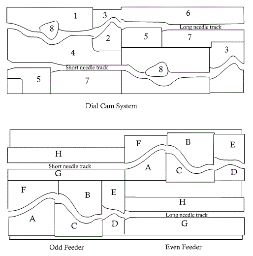
    In the figure the cylinder and dial camming to produce one course of ordinary interlock fabric which is actually work of two knitting feeders.

    The cylinder cam:

    A → clearing cam which lifts the needles to clear the old loop
    B, C → stitch cam and guard cams respectively both vertically adjustable to control the stitch length.
    D → up through to rise the needle whilst dial needle knock over
    E, F → guard cam to complete the truck
    G, H → guide cam to provide the track for idling needles
     

    Cylinder Cam System
    The dial system:
    1. Raising cam for tuck position only
    2, 3. Dial knock over cam
    4. Guard cam to compete the truck
    5. Auxiliary knock over cam to prevent the dial needle reentering the old loop
    6, 7 Guide cams provides the tracks for idling needles
    8. Sewing type clearing cam which may occupy the knitting position as shown in feeder 1 or in tuck position at feeder 2.

    Machine parts:

    1.  Yarn career 
    2.  Break stop motion 
    3.  Yarn guides 
    4.  Dial 
    5.  Cylinder 
    6.  Dial cams 
    7.  Cylinder cams 
    8.  Dial needles 
    9.  Cylinder needles 
    10.  Oiling and air following devices 
    11.  Sensors 
    12.  Take up rollers 
    13.  Batch rollers 
    14.  Motor 
    15.  Belts 
    16.  Pulleys and gears  Clutches
    Knitting action: 

    Conclusion:
    The circular Interlock machine is a very commonly used machine in country to make Interlock knitted fabric. So this experiment has significance in our study life. In this experiment we sketch the yarn path diagram of the machine, show the knitting action, cam system. We point out the various specification of the machine. So the experiment helps us to know more.

    Above all the experiment is a successful one.

    Interlock Circular Knitting Machine | Knitting Action of InterlockCircular Knitting Machine

    Posted at  04:28  |  in  regular  |  Continue lendo ...»

    Name of the Experiment: Study on interlock circular knitting machine.

    OBJECTS:
    1.To have the idea about an interlock m/c .
    2.To know about its working principles.

    Introduction:
    Interlock structure is a double faced Interlock structure which consists of two 1×1 Interlock structures. These two 1×1 Interlock structures are joined by interlocking sinker loops and thus produce interlock structure. Interlock structure is produce by special cylinder dial circular machines. Double system V-bed flat knitting machine also used to produce interlock structure.

    SPECIFICATIONS:

    1. Machine name: Interlock Circular Knitting Machine.
    2. Company:- Precision FUKUHARA Works Limited.
    3. Origin of the machine:- Japan
    4. Model no. :- V 8ME 42 
    5. Dia of the machine:- 30”.
    6. Gauge of the machine:- 22 
    7. No of Feeder:- 84 
    8. Serial no:- 1352761.
    9. Creel Capacity: 84.
    10. Feeding: Positive.
    MACHINE PARTS:
    1.Yarn career
    2.Break stop motion
    3.Yarn guides
    4.Dial
    5.Cylinder
    6.Dial cams
    7.Cylinder cams
    8.Dial needles
    9.Cylinder needles
    10.Oiling and air following devices
    11.Sensors
    12.Take up rollers
    13.Batch rollers
    14.Motor
    15.Belts 16.Clutches
    17.Pulleys and gears

    Machine description:
    The machine has two sets of needles on two different beds, one set on cylinder one in the dial bed. These two sets of needles must be exactly opposite to each other.

    The machine has two separate cam system in each bed needles of different length called short needles and long needles. Each cam system controls half of the needles in alternate sequences. One cam system controls knitting at one feeder and other ca, system controls at the next feeders. T ale down mechanism is the same as the other Interlock and plain machines mechanism.

    Interlock cam system:
    In the figure the cylinder and dial camming to produce one course of ordinary interlock fabric which is actually work of two knitting feeders.

    The cylinder cam:

    A → clearing cam which lifts the needles to clear the old loop
    B, C → stitch cam and guard cams respectively both vertically adjustable to control the stitch length.
    D → up through to rise the needle whilst dial needle knock over
    E, F → guard cam to complete the truck
    G, H → guide cam to provide the track for idling needles
     

    Cylinder Cam System
    The dial system:
    1. Raising cam for tuck position only
    2, 3. Dial knock over cam
    4. Guard cam to compete the truck
    5. Auxiliary knock over cam to prevent the dial needle reentering the old loop
    6, 7 Guide cams provides the tracks for idling needles
    8. Sewing type clearing cam which may occupy the knitting position as shown in feeder 1 or in tuck position at feeder 2.

    Machine parts:

    1.  Yarn career 
    2.  Break stop motion 
    3.  Yarn guides 
    4.  Dial 
    5.  Cylinder 
    6.  Dial cams 
    7.  Cylinder cams 
    8.  Dial needles 
    9.  Cylinder needles 
    10.  Oiling and air following devices 
    11.  Sensors 
    12.  Take up rollers 
    13.  Batch rollers 
    14.  Motor 
    15.  Belts 
    16.  Pulleys and gears  Clutches
    Knitting action: 

    Conclusion:
    The circular Interlock machine is a very commonly used machine in country to make Interlock knitted fabric. So this experiment has significance in our study life. In this experiment we sketch the yarn path diagram of the machine, show the knitting action, cam system. We point out the various specification of the machine. So the experiment helps us to know more.

    Above all the experiment is a successful one.

    Experiment Name: Study on knitting action of Tricot warp knitting machine.

    Introduction:
    The warp knitting machine is a knitting m/c where the loops are formed in course wise direction and the fabric produced is in open width form. In Tricot warp knitting m/c compound needles are used. The warp yarns are feed to the needles through guide bars using shogging and swinging motion.

    M/C specification:

    1. Brand: LIBA
    2. Origin: W. Germany
    3. Manufacturing Company: MASCHINEN FABRIK, NAILA.
    4. Manufacturing Year: 1991 
    5. Width: 84 inch/ 213 cm
    6. Type: COP 2K
    7. Gauge: 28 
    Knitting Action:
    1. The rest position: Te needles have risen to 2/3 of their full height from knock-over and have their hooks towards the back of the m/c. The latch bar is in downward position and the guides are at the front of the m/c with the sinkers forward, holding the old overlaps in their throats so that they are maintained in the correct height on the needle stems.

    2. Needle rise and guide bar swing: With the sinkers forward holding down the fabric, the hooks and tongues rise, with the hook rising faster, until the head of the latter is level with the guide holes and is open. The guides then swing through to the back of the m/c.

    3. The overlap and return swing: The guide’s shog for the overlap and swing to the front of the m/c immediately. The hooks and the tongues start to descend with the tongues descending more slowly, thus closing the hook.

    4. Hook closing: The hooks and the tongues start to descend with the tongues descending more slowly, thus closing the hook

    5. Landing:
    The sinkers start to withdraw as the needles descend so that the old loop is landed onto the closed hook. Thus the landing is occurred.

    6. Knock-over and under lap: The sinkers start to withdraw as the needles descend so that the old loop is landed onto the closed hook and then knocked over as it descends below the sinker belly. At this point the under lap occurs before the needles begin their upward rise and sinker move forward to hold down the fabric.

    7. The sinkers now move forward to hold down the fabric loops and push them away from the ascending needles, which are rising to the rest position.

    Conclusion:
    The knitting action of the Tricot warp knitting m/c is done by the needles, its sliding latches and the guide bars. The main work of feeding the thread around the needle is done by guides with their shogging and swinging motions. By this experiment I learned about the knitting action of a tricot warp knitting machine. This experience will help me in my future practical life.

    Knitting Action of Tricot Warp Knitting Machine

    Posted at  03:56  |  in  Warp Knitting  |  Continue lendo ...»

    Experiment Name: Study on knitting action of Tricot warp knitting machine.

    Introduction:
    The warp knitting machine is a knitting m/c where the loops are formed in course wise direction and the fabric produced is in open width form. In Tricot warp knitting m/c compound needles are used. The warp yarns are feed to the needles through guide bars using shogging and swinging motion.

    M/C specification:

    1. Brand: LIBA
    2. Origin: W. Germany
    3. Manufacturing Company: MASCHINEN FABRIK, NAILA.
    4. Manufacturing Year: 1991 
    5. Width: 84 inch/ 213 cm
    6. Type: COP 2K
    7. Gauge: 28 
    Knitting Action:
    1. The rest position: Te needles have risen to 2/3 of their full height from knock-over and have their hooks towards the back of the m/c. The latch bar is in downward position and the guides are at the front of the m/c with the sinkers forward, holding the old overlaps in their throats so that they are maintained in the correct height on the needle stems.

    2. Needle rise and guide bar swing: With the sinkers forward holding down the fabric, the hooks and tongues rise, with the hook rising faster, until the head of the latter is level with the guide holes and is open. The guides then swing through to the back of the m/c.

    3. The overlap and return swing: The guide’s shog for the overlap and swing to the front of the m/c immediately. The hooks and the tongues start to descend with the tongues descending more slowly, thus closing the hook.

    4. Hook closing: The hooks and the tongues start to descend with the tongues descending more slowly, thus closing the hook

    5. Landing:
    The sinkers start to withdraw as the needles descend so that the old loop is landed onto the closed hook. Thus the landing is occurred.

    6. Knock-over and under lap: The sinkers start to withdraw as the needles descend so that the old loop is landed onto the closed hook and then knocked over as it descends below the sinker belly. At this point the under lap occurs before the needles begin their upward rise and sinker move forward to hold down the fabric.

    7. The sinkers now move forward to hold down the fabric loops and push them away from the ascending needles, which are rising to the rest position.

    Conclusion:
    The knitting action of the Tricot warp knitting m/c is done by the needles, its sliding latches and the guide bars. The main work of feeding the thread around the needle is done by guides with their shogging and swinging motions. By this experiment I learned about the knitting action of a tricot warp knitting machine. This experience will help me in my future practical life.

    Super Ofertas

    --
    Copyright © 2013 fibres2fashion. Blogger Template by BloggerTheme9
    Proudly Powered by Blogger.
    back to top
