• Em Destaque

    Aqui Você Encontra Os Melhores Template da Internet .

  • Em Destaque

    Aqui Você Encontra Os Melhores Template da Internet .

  • Em Destaque

    Aqui Você Encontra Os Melhores Template da Internet .

  • Em Destaque

    Aqui Você Encontra Os Melhores Template da Internet .

  • Curte aí!

    Showing posts with label Ring Frame. Show all posts
    Showing posts with label Ring Frame. Show all posts

    Thursday, 15 March 2012

    Traveller
    Traveller is a tiny element which is used in ring spinning system , acts as the main of twist imparter during yarn production. On the other word , it is also called the twisting element merely responsible for twist impartion.It is a C-shaped, metal clip that revolves around the ring on a ring spinning frame. It guides the yarn onto the bobbin as twist is inserted into the yarn.

    Ring Traveller
    The traveller allows the twisting and the correct delivery of the yarn on the bobbin. The take up speed of the yarn, which corresponds to the difference between the peripheral speed of the bobbin and the peripheral speed of the traveller, is equal to the peripheral speed of the delivery cylinders of the drafting unit. The difference between spindle rpm and the traveler rpm, within a specific unit of time, gives the number of coils deposited on the bobbin within a specific unit of time. Therefore, with the same spindle speed, the traveller rpm increases along with the bobbin diameter while the number of coils wound on the bobbin decreases.

    When the traveller rotates the high contact pressure between the ring and the traveller creates huge friction forces that generate heat; the traveller can reach temperatures exceeding 200 ÷ 300 °C since its small mass does not allow a quick transfer of the heat to the air or to the ring. For this reason, significant improvements in ring spinning can be hardly achieved with the materials currently available, since the speed of the traveller has apparently reached its maximum limit (approx. 33 ÷ 35 m/sec for steel travellers and 45 ÷ 47 m/s for nylon-glass fibre travellers). This is why the traveller used for producing a specific type of yarn must feature the most suitable shape, mass, material, finish and cross section. To reach the highest speeds, the shape of the traveller must correspond to the shape of the ring.

    This creates a very large contact surface, which facilitates heat transfer; the surface must also be very smooth to grant a low barycentre. The flat profile must allow space enough for the yarn since the friction between the yarn and the ring could increase the yarn hairiness and consequently the formation of flying fibres.

    The mass of the traveller determines the friction force between the ring and the traveller, the balloon size and consequently the take up tension of the yarn. If the mass of the traveller is very small, the balloon will be sufficiently large, the take up tension will be limited and the bobbin will be soft; on the contrary, a heavy traveller will determine an increase in the take up tension and a greater number of breaks. In a few words, the mass of the traveller must be strictly proportional to the yarn mass (count and resistance) and to the speed of the spindle. 
    Features of a Traveller:
    1. Generate less heat
    2. Dissipate heat fastly
    3. Have sufficient elasticity for easy insertion and to retain its original shape after insertion
    4. Friction between ring and traveller should be minimal
    5. It should have excellent wear resistance for longer life
    6. Hardness of the traveller should be less than the ring
    Types of Traveller:
    Traveller are normally three types. They are:
    1. OS -Type
    2. C-Type
    3. G-Type
    Factors for Ring Traveller Selection :
    1. Count of yarn to be spun
    2. Fiber used in the yarn
    3. Ring cup diameter
    4. Spindle speed

    Ring Traveller | Features of a Ring Traveller | Types of Traveller |Factors for Ring Traveller Selection

    Posted at  05:57  |  in  Spinning  |  Continue lendo ...»

    Traveller
    Traveller is a tiny element which is used in ring spinning system , acts as the main of twist imparter during yarn production. On the other word , it is also called the twisting element merely responsible for twist impartion.It is a C-shaped, metal clip that revolves around the ring on a ring spinning frame. It guides the yarn onto the bobbin as twist is inserted into the yarn.

    Ring Traveller
    The traveller allows the twisting and the correct delivery of the yarn on the bobbin. The take up speed of the yarn, which corresponds to the difference between the peripheral speed of the bobbin and the peripheral speed of the traveller, is equal to the peripheral speed of the delivery cylinders of the drafting unit. The difference between spindle rpm and the traveler rpm, within a specific unit of time, gives the number of coils deposited on the bobbin within a specific unit of time. Therefore, with the same spindle speed, the traveller rpm increases along with the bobbin diameter while the number of coils wound on the bobbin decreases.

    When the traveller rotates the high contact pressure between the ring and the traveller creates huge friction forces that generate heat; the traveller can reach temperatures exceeding 200 ÷ 300 °C since its small mass does not allow a quick transfer of the heat to the air or to the ring. For this reason, significant improvements in ring spinning can be hardly achieved with the materials currently available, since the speed of the traveller has apparently reached its maximum limit (approx. 33 ÷ 35 m/sec for steel travellers and 45 ÷ 47 m/s for nylon-glass fibre travellers). This is why the traveller used for producing a specific type of yarn must feature the most suitable shape, mass, material, finish and cross section. To reach the highest speeds, the shape of the traveller must correspond to the shape of the ring.

    This creates a very large contact surface, which facilitates heat transfer; the surface must also be very smooth to grant a low barycentre. The flat profile must allow space enough for the yarn since the friction between the yarn and the ring could increase the yarn hairiness and consequently the formation of flying fibres.

    The mass of the traveller determines the friction force between the ring and the traveller, the balloon size and consequently the take up tension of the yarn. If the mass of the traveller is very small, the balloon will be sufficiently large, the take up tension will be limited and the bobbin will be soft; on the contrary, a heavy traveller will determine an increase in the take up tension and a greater number of breaks. In a few words, the mass of the traveller must be strictly proportional to the yarn mass (count and resistance) and to the speed of the spindle. 
    Features of a Traveller:
    1. Generate less heat
    2. Dissipate heat fastly
    3. Have sufficient elasticity for easy insertion and to retain its original shape after insertion
    4. Friction between ring and traveller should be minimal
    5. It should have excellent wear resistance for longer life
    6. Hardness of the traveller should be less than the ring
    Types of Traveller:
    Traveller are normally three types. They are:
    1. OS -Type
    2. C-Type
    3. G-Type
    Factors for Ring Traveller Selection :
    1. Count of yarn to be spun
    2. Fiber used in the yarn
    3. Ring cup diameter
    4. Spindle speed

    Monday, 13 February 2012

    Experiment Name: Study on ring doubling frame
    1.Spindle speed, front roller delivery.
    2.Twist, twist Constant.

    Objects:

    1) To combine two or more single threads into one.
    2) To insert sufficient amount of twist for holding the yarns.
    3) To increase strength, smoothness and luster.
    4) To reduce hairiness.
    5) To make sewing thread.
    6) To wind a suitable bobbin.

    Main parts:  
    1. Creel stand and creel. 
    2. Front roller. 
    3. Yarn guide. 
    4. Ring and ring rail  
    5. Tin cylinder. 
    6. Traveller.  
    7. Thread weight or slip roller. 
    8.  Lappet  Spindle.
    Specification:
    • Motor rpm = 1430 
    • Motor pulley diameter = 6.25²
    • Machine pulley diameter = 10.25²
    • Tin cylinder diameter = 10²
    • Wharve diameter = 1.37²
    • Cylinder carrier wheel = 24T
    • TCP carrier wheel = 62T
    • TCP = 63T
    • Front roller diameter = 2’’
    Calculation:
    Gearing diagram of doubling frame: 
     

    Figure: gearing diagram of doubling frame.
    Result:
    1) Spindle speed = 6461.59 rpm
    2) Twist constant = 1235.25
    3) Front roller delivery = 319.143 inch/min.
    4) Existing TPI =
    20
    5) Production = 14.37 lb/shift/frame.
    6) Required TPI = 16.266

    7) Required TCP =76.25T

    Conclusion: 
    By this experiment we come to know about various parts and working principle of ring doubling frame. This machine is important for producing double yarn on sewing thread.

    Doubling in Ring Frame | Study on Ring Doubling Frame

    Posted at  23:49  |  in  Twist  |  Continue lendo ...»

    Experiment Name: Study on ring doubling frame
    1.Spindle speed, front roller delivery.
    2.Twist, twist Constant.

    Objects:

    1) To combine two or more single threads into one.
    2) To insert sufficient amount of twist for holding the yarns.
    3) To increase strength, smoothness and luster.
    4) To reduce hairiness.
    5) To make sewing thread.
    6) To wind a suitable bobbin.

    Main parts:  
    1. Creel stand and creel. 
    2. Front roller. 
    3. Yarn guide. 
    4. Ring and ring rail  
    5. Tin cylinder. 
    6. Traveller.  
    7. Thread weight or slip roller. 
    8.  Lappet  Spindle.
    Specification:
    • Motor rpm = 1430 
    • Motor pulley diameter = 6.25²
    • Machine pulley diameter = 10.25²
    • Tin cylinder diameter = 10²
    • Wharve diameter = 1.37²
    • Cylinder carrier wheel = 24T
    • TCP carrier wheel = 62T
    • TCP = 63T
    • Front roller diameter = 2’’
    Calculation:
    Gearing diagram of doubling frame: 
     

    Figure: gearing diagram of doubling frame.
    Result:
    1) Spindle speed = 6461.59 rpm
    2) Twist constant = 1235.25
    3) Front roller delivery = 319.143 inch/min.
    4) Existing TPI =
    20
    5) Production = 14.37 lb/shift/frame.
    6) Required TPI = 16.266

    7) Required TCP =76.25T

    Conclusion: 
    By this experiment we come to know about various parts and working principle of ring doubling frame. This machine is important for producing double yarn on sewing thread.

    Name of the experiment: Calculation of twist, twist constant of the ring frame.

    Objects:
    i) To find out twist per inch of the ring frame.
    ii) To find out twist constant of the ring frame.

    Specification:
    Front roller diameter =  1”
    Tin cylinder diameter =  10”
    Whrave diameter = 1.125”
    Twist change pinion = 48T

    Gearing diagram:
    Figure: gearing diagram for calculating twist and twist constant of ring frame.
    Calculation:

    Result:
    1) TPI= 21
    2) Twist constant= 1008

    Conclusion:
    Ring frame is the final and very important machine for build the yarn onto bobbin in a form suitable for storage, transportation and processing. It is used to twist the drafted strand to form yarn of required count and strength. In this practical we calculate twist, twist constant of the ring frame. By this practical we come to know about the gearing diagram of ring frame. Special thanks to our teacher and his assistance for helping us.

    Calculation of Twist, Twist Constant of the Ring Frame

    Posted at  23:22  |  in  Twist  |  Continue lendo ...»

    Name of the experiment: Calculation of twist, twist constant of the ring frame.

    Objects:
    i) To find out twist per inch of the ring frame.
    ii) To find out twist constant of the ring frame.

    Specification:
    Front roller diameter =  1”
    Tin cylinder diameter =  10”
    Whrave diameter = 1.125”
    Twist change pinion = 48T

    Gearing diagram:
    Figure: gearing diagram for calculating twist and twist constant of ring frame.
    Calculation:

    Result:
    1) TPI= 21
    2) Twist constant= 1008

    Conclusion:
    Ring frame is the final and very important machine for build the yarn onto bobbin in a form suitable for storage, transportation and processing. It is used to twist the drafted strand to form yarn of required count and strength. In this practical we calculate twist, twist constant of the ring frame. By this practical we come to know about the gearing diagram of ring frame. Special thanks to our teacher and his assistance for helping us.

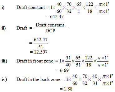
    Name of the experiment: Calculation of draft, draft constant and draft in each zone of the ring frame.

    Objects:

    1) To find out draft, draft constant of the ring frame.
    2) To find out draft of each zone of the ring frame.

    M/C specifications:

    • RPM of the motor =1440 
    • Dia of the motor pulley = 5”
    • Dia of the tin cylinder pulley = 10.5”
    • Dia of the tin cylinder = 10”
    • Dia of the wharve = 1.125”
    • No of teeth of fibre wheel = 42T
    • No of teeth of front roller driving wheel = 98T
    • Dia of the front roller = 1”
    Gearing diagram:
    Figure :- Gearing Diagram of Drafting Zone of Speed Frame Machine
    Calculation of draft, draft constant and draft of each zone of the ring frame:

     
    Conclusion:
    Ring frame is the final and very important machine for build the yarn onto bobbin in a form suitable for storage, transportation and processing. It is used to twist the drafted strand to form yarn of required count and strength.


    Calculation of Draft, Draft Constant of Ring Frame

    Posted at  23:00  |  in  Spinning  |  Continue lendo ...»

    Name of the experiment: Calculation of draft, draft constant and draft in each zone of the ring frame.

    Objects:

    1) To find out draft, draft constant of the ring frame.
    2) To find out draft of each zone of the ring frame.

    M/C specifications:

    • RPM of the motor =1440 
    • Dia of the motor pulley = 5”
    • Dia of the tin cylinder pulley = 10.5”
    • Dia of the tin cylinder = 10”
    • Dia of the wharve = 1.125”
    • No of teeth of fibre wheel = 42T
    • No of teeth of front roller driving wheel = 98T
    • Dia of the front roller = 1”
    Gearing diagram:
    Figure :- Gearing Diagram of Drafting Zone of Speed Frame Machine
    Calculation of draft, draft constant and draft of each zone of the ring frame:

     
    Conclusion:
    Ring frame is the final and very important machine for build the yarn onto bobbin in a form suitable for storage, transportation and processing. It is used to twist the drafted strand to form yarn of required count and strength.


    Experiment name: Study on the gearing diagram, calculation of spindle speed and front roller speed of the ring frame.

    Object:

    1. To know about the different parts of the ring frame.
    2. To know about the function of the different parts of the ring frame machine.
    3. To know about the driving mechanism of the spindle
    4. To calculate the front roller delivery of the machine
    5. To study the machine in order to improve our technical knowledge.

    Gearing Diagram
    Ring Frame:
    Fig: Gearing diagram of ring frame
    Machine specification:
    • RPM of the motor = 1440 
    • Diameter of the motor pulley = 5″
    • Diameter of the tin cylinder pulley = 10.5″
    • Diameter of the tin cylinder = 10″
    • Diameter of the wharve = 1.125″
    • No of teeth of lower grip wheel = 26T
    • No of teeth of upper grip wheel = 46T
    • No of teeth of fibre wheel = 42T
    • No of teeth of twist carrier wheel = 86T
    • No of teeth of twist wheel = 48T
    • No of teeth of front roller driving wheel = 98T
    • Diameter of front roller = 1″
    Calculation:

    Result:
    Spindle Speed = 6095.24 rpm
    Front roller delivery = 323.56 inch/min

    Conclusion:

    Our teacher and lab assistants are very much helpful to us. Their well teaching and instruction help us greatly to understand this practical. I think this practical will be very helpful in my future career.


    Calculation of Spindle Speed and Front Roller Speed of the Ring Frame | Gearing Diagram of Ring Frame

    Posted at  22:36  |  in  Spinning M/C  |  Continue lendo ...»

    Experiment name: Study on the gearing diagram, calculation of spindle speed and front roller speed of the ring frame.

    Object:

    1. To know about the different parts of the ring frame.
    2. To know about the function of the different parts of the ring frame machine.
    3. To know about the driving mechanism of the spindle
    4. To calculate the front roller delivery of the machine
    5. To study the machine in order to improve our technical knowledge.

    Gearing Diagram
    Ring Frame:
    Fig: Gearing diagram of ring frame
    Machine specification:
    • RPM of the motor = 1440 
    • Diameter of the motor pulley = 5″
    • Diameter of the tin cylinder pulley = 10.5″
    • Diameter of the tin cylinder = 10″
    • Diameter of the wharve = 1.125″
    • No of teeth of lower grip wheel = 26T
    • No of teeth of upper grip wheel = 46T
    • No of teeth of fibre wheel = 42T
    • No of teeth of twist carrier wheel = 86T
    • No of teeth of twist wheel = 48T
    • No of teeth of front roller driving wheel = 98T
    • Diameter of front roller = 1″
    Calculation:

    Result:
    Spindle Speed = 6095.24 rpm
    Front roller delivery = 323.56 inch/min

    Conclusion:

    Our teacher and lab assistants are very much helpful to us. Their well teaching and instruction help us greatly to understand this practical. I think this practical will be very helpful in my future career.


    Experiment name: Study on the material passage of Ring frame.

    Object:
    1. To produce required count of yarn from the supplied roving by the drafting.

    2. To insert sufficient amount of twist to the yarn.
    3. To wind the yarn onto the bobbin.
    4. To build the yarn package properly.

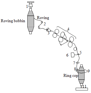
    Main Parts Ring Frame:

    1. Creel

    2. Guide roller
    3. Trumpet
    4. Drafting rollers
    5. Yarn guide
    6. Lappet
    7. Balloon controlling ring
    8. Traveler
    9. Ring
    10. Spindle

    Specification:

    I. Name of manufacturer: Platts.
    II. No of spindle: 64 
    III. Ring dia: 6.2 cm
    IV. Lift of the bobbin: 9”

    Passage diagram:
    Fig: Passage Diagram of Ring frame
    Description:
    The feed material come from speed frame i.e. roving bobbin is placed on the creel. The creel which is attached to the machine is umbrella type. Then feed material is passed under the guide rollers and through the trumpet in to the drafting zone. Here some draft is inserted in to the roving. The draft system is 3 over 3 drafting system with apron. The delivery material that is delivered from the front roller is reached to the traveler over pneumatic waste collector, lappet and through balloon controlling ring. Lappet is used to control the material path and balloon controlling ring is used to control the balloon formation and spinning tension. Here roving is twisted by the movement of the traveler around the ring. The yarn is then wound on the ring cop.

    Conclusion:

    Our teacher and lab assistants are very much helpful to us. Their well teaching and instruction help us greatly to understand this practical. I think this practical will be very helpful in my future career.


    Ring Frame | Material Passage Diagram of Ring Frame

    Posted at  21:07  |  in  Spinning M/C  |  Continue lendo ...»

    Experiment name: Study on the material passage of Ring frame.

    Object:
    1. To produce required count of yarn from the supplied roving by the drafting.

    2. To insert sufficient amount of twist to the yarn.
    3. To wind the yarn onto the bobbin.
    4. To build the yarn package properly.

    Main Parts Ring Frame:

    1. Creel

    2. Guide roller
    3. Trumpet
    4. Drafting rollers
    5. Yarn guide
    6. Lappet
    7. Balloon controlling ring
    8. Traveler
    9. Ring
    10. Spindle

    Specification:

    I. Name of manufacturer: Platts.
    II. No of spindle: 64 
    III. Ring dia: 6.2 cm
    IV. Lift of the bobbin: 9”

    Passage diagram:
    Fig: Passage Diagram of Ring frame
    Description:
    The feed material come from speed frame i.e. roving bobbin is placed on the creel. The creel which is attached to the machine is umbrella type. Then feed material is passed under the guide rollers and through the trumpet in to the drafting zone. Here some draft is inserted in to the roving. The draft system is 3 over 3 drafting system with apron. The delivery material that is delivered from the front roller is reached to the traveler over pneumatic waste collector, lappet and through balloon controlling ring. Lappet is used to control the material path and balloon controlling ring is used to control the balloon formation and spinning tension. Here roving is twisted by the movement of the traveler around the ring. The yarn is then wound on the ring cop.

    Conclusion:

    Our teacher and lab assistants are very much helpful to us. Their well teaching and instruction help us greatly to understand this practical. I think this practical will be very helpful in my future career.


    Super Ofertas

    --
    Copyright © 2013 fibres2fashion. Blogger Template by BloggerTheme9
    Proudly Powered by Blogger.
    back to top