• Em Destaque

    Aqui Você Encontra Os Melhores Template da Internet .

  • Em Destaque

    Aqui Você Encontra Os Melhores Template da Internet .

  • Em Destaque

    Aqui Você Encontra Os Melhores Template da Internet .

  • Em Destaque

    Aqui Você Encontra Os Melhores Template da Internet .

  • Curte aí!

    Showing posts with label Knitting M/C. Show all posts
    Showing posts with label Knitting M/C. Show all posts

    Monday, 12 March 2012

    Raschel machines (Figures A and B) originally had a gauge expressed in needles per 2 inches (5 cm), so that, for example, a 36-gauge raschel would have eighteen needles per inch. Now, the standard E gauge (needles per inch) is generally used. There is a wide gauge range, from E 1 to E 32.

    Their chain links are usually numbered in even numbers, 0, 2, 4, 6 etc., generally with two links per course. Raschel sinkers perform only the function of holding down the loops whilst the needles rise.They are not joined together by a lead across their ends nearest to the needle bar so they can move away clear of the needles, towards the back of the machine, for the rest of the knitting cycle.The needle trick plate verge acts as a fabric support ledge and knock-over surface.

    The fabric is drawn downwards from the needles, almost parallel to the needle bar, at an angle of 120–160 degrees, by a series of take-down rollers. This creates a high take-up tension, particularly suitable for open fabric structures such as laces and nets. 

    Fig. A. Knitting elements in a latch needle raschel machine

    Fig. B. Cross-section of a latch needle raschel machine
    The warp beams are arranged above the needle bar, centred over the rocker shaft, so that warp sheets pass down to the guide bars on either side of it.The beams are placed above the machine so that it is accessible at the front for fabric inspection and at the back for mechanical attention to the knitting elements. The guide bars are threaded, commencing with the middle bars and working outwards from either side of the rocker-shaft. They are numbered from the front of the machine.

    With the raschel arrangement, there is accommodation for at least four 32-inch diameter beams or large numbers of small diameter pattern bars. The accessibility of the raschel machine, its simple knitting action, and its strong and efficient take-down tension make it particularly suitable for the production of coarse gauge open-work structures employing pillar stitch, inlay lapping variations and partlythreaded guide bars. These are difficult to knit and hold down with the tricot arrangement of sinkers. Additional warp threads may be supplied at the selvedges to ensure that these needles knit fabric overlaps, otherwise a progressive press-off of loops may occur.

    Knitting Elements in a Latch Needle Raschel Machine | Cross-section ofa Latch Needle Raschel Machine

    Posted at  05:22  |  in  regular  |  Continue lendo ...»

    Raschel machines (Figures A and B) originally had a gauge expressed in needles per 2 inches (5 cm), so that, for example, a 36-gauge raschel would have eighteen needles per inch. Now, the standard E gauge (needles per inch) is generally used. There is a wide gauge range, from E 1 to E 32.

    Their chain links are usually numbered in even numbers, 0, 2, 4, 6 etc., generally with two links per course. Raschel sinkers perform only the function of holding down the loops whilst the needles rise.They are not joined together by a lead across their ends nearest to the needle bar so they can move away clear of the needles, towards the back of the machine, for the rest of the knitting cycle.The needle trick plate verge acts as a fabric support ledge and knock-over surface.

    The fabric is drawn downwards from the needles, almost parallel to the needle bar, at an angle of 120–160 degrees, by a series of take-down rollers. This creates a high take-up tension, particularly suitable for open fabric structures such as laces and nets. 

    Fig. A. Knitting elements in a latch needle raschel machine

    Fig. B. Cross-section of a latch needle raschel machine
    The warp beams are arranged above the needle bar, centred over the rocker shaft, so that warp sheets pass down to the guide bars on either side of it.The beams are placed above the machine so that it is accessible at the front for fabric inspection and at the back for mechanical attention to the knitting elements. The guide bars are threaded, commencing with the middle bars and working outwards from either side of the rocker-shaft. They are numbered from the front of the machine.

    With the raschel arrangement, there is accommodation for at least four 32-inch diameter beams or large numbers of small diameter pattern bars. The accessibility of the raschel machine, its simple knitting action, and its strong and efficient take-down tension make it particularly suitable for the production of coarse gauge open-work structures employing pillar stitch, inlay lapping variations and partlythreaded guide bars. These are difficult to knit and hold down with the tricot arrangement of sinkers. Additional warp threads may be supplied at the selvedges to ensure that these needles knit fabric overlaps, otherwise a progressive press-off of loops may occur.

    Sunday, 11 March 2012


    Fig: Knitting action of bearded needle simplex machine
    Figure: Shows the knitting action on the front needle bar; an identical sequence occurs afterwards on the back needle bar to complete the machine cycle.

    (a) First rise of the needle bar. The knitting action has been completed on the back needle bar for the previous machine cycle. The front sinker/presser bar has withdrawn, leaving the back sinker bar to support the fabric. The guide bars have completed their third swinging movement so that they are now swinging towards the back of the machine, allowing the front needle bar to rise with the back needle bar still near to knock-over and thus helping to hold down the fabric. The front needle bar rises sufficiently to enable the old overlaps under the beards to slide down onto the needle stems.

    (b) Return swing, second rise then lowering and pressing. As the guides swing to the back of the machine, the warp ends are wrapped over the needle beards. The front needle bar is now lifted to a higher position so that the new overlaps slip from the beards to a high position on the needle stems. As the front needle bar is lowered to cover the new overlaps, the front sinker presser bar moves to contact and press the beards so that the old overlaps slide onto the closed beards which descend through them.

    (c) Completion of landing and knock-over, underlap and third guide bar swing. Whilst the needles descend further to knock-over the old overlaps, the guide bars make their underlap shog behind the front needle bar and then commence their swing towards the front of the machine to allow the back needle bar to rise for the second part of the machine sequence.

    Knitting Action of Bearded Needle Simplex Machine

    Posted at  05:26  |  in  regular  |  Continue lendo ...»


    Fig: Knitting action of bearded needle simplex machine
    Figure: Shows the knitting action on the front needle bar; an identical sequence occurs afterwards on the back needle bar to complete the machine cycle.

    (a) First rise of the needle bar. The knitting action has been completed on the back needle bar for the previous machine cycle. The front sinker/presser bar has withdrawn, leaving the back sinker bar to support the fabric. The guide bars have completed their third swinging movement so that they are now swinging towards the back of the machine, allowing the front needle bar to rise with the back needle bar still near to knock-over and thus helping to hold down the fabric. The front needle bar rises sufficiently to enable the old overlaps under the beards to slide down onto the needle stems.

    (b) Return swing, second rise then lowering and pressing. As the guides swing to the back of the machine, the warp ends are wrapped over the needle beards. The front needle bar is now lifted to a higher position so that the new overlaps slip from the beards to a high position on the needle stems. As the front needle bar is lowered to cover the new overlaps, the front sinker presser bar moves to contact and press the beards so that the old overlaps slide onto the closed beards which descend through them.

    (c) Completion of landing and knock-over, underlap and third guide bar swing. Whilst the needles descend further to knock-over the old overlaps, the guide bars make their underlap shog behind the front needle bar and then commence their swing towards the front of the machine to allow the back needle bar to rise for the second part of the machine sequence.

    Saturday, 10 March 2012

    Figure: illustrates the knitting action of a crochet machine:
    1. The inlay.Whilst the needle is withdrawn into its trick during knock-over of the previous warp overlap, the weft inlay tube is lowered. As it traverses in an underlap shog, the weft is laid below the level of the needle and on top of the warp thread that extends from its head to the warp guide.

    2. Clearing the warp overlap. The weft tube rises slightly on completion of its traverse movement to allow the needle to move out of its trick to clear its old warp overlap.

    3. The warp overlap wrap. The warp guide rises between the needles and automatically overlaps from the left, lowering itself again on the right side of its needle.

    4. Warp knock-over and underlap. The needle now retires into its trick to knockover the old overlap, whilst the warp guide is cammed under its needle to the start position for its next overlap, thus completing the closed lap pillar. NB:The closed lap is used for the carbine needle but the alternating overlap of the open lap pillar stitch used with the conventional latch and bearded needles gives a more balanced loop structure. Tricot lapping with two guide bars produces a secure fabric which does not unrove.

    Knitting Action of the Crochet Machine

    Posted at  02:24  |  in  regular  |  Continue lendo ...»

    Figure: illustrates the knitting action of a crochet machine:
    1. The inlay.Whilst the needle is withdrawn into its trick during knock-over of the previous warp overlap, the weft inlay tube is lowered. As it traverses in an underlap shog, the weft is laid below the level of the needle and on top of the warp thread that extends from its head to the warp guide.

    2. Clearing the warp overlap. The weft tube rises slightly on completion of its traverse movement to allow the needle to move out of its trick to clear its old warp overlap.

    3. The warp overlap wrap. The warp guide rises between the needles and automatically overlaps from the left, lowering itself again on the right side of its needle.

    4. Warp knock-over and underlap. The needle now retires into its trick to knockover the old overlap, whilst the warp guide is cammed under its needle to the start position for its next overlap, thus completing the closed lap pillar. NB:The closed lap is used for the carbine needle but the alternating overlap of the open lap pillar stitch used with the conventional latch and bearded needles gives a more balanced loop structure. Tricot lapping with two guide bars produces a secure fabric which does not unrove.

    Thursday, 8 March 2012

    Fig.A:Knitting Cycle of the Bearded Needle Tricot Machine

    Figure.A: illustrates the knitting cycle of the bearded needle tricot machine

    1. The rest position (a). The needles have risen to 2/3 of their full height from knock-over and have their beards towards the back of the machine.The presser is withdrawn and the guides are at the front of the machine with the sinkers forward, holding the old overlaps in their throats so that they are maintained at the correct height on the needle stems.

    2. Backward swing and overlap shog (b, c). After swinging through the needles to the beard side, the guides are overlapped across the beards, usually by one needle space in opposite directions.

    3. The return swing and second rise (c, d). As the guides swing to the front, the needles rise to their full height so that the newly-formed overlaps slip off the beards onto the stems above the old overlaps. This arrangement reduces the amount of guide-bar swing necessary and therefore the time required.

    4. Pressing (e). The needle bar descends so that the open beards cover the new overlaps. There is a slight pause whilst the presser advances and closes the beards.

    5. Landing (f). As the sinkers withdraw, the upward curve of their bellies lands the old overlaps onto the closed beards.

    6. Knock-over and underlap shog (g). The presser is withdrawn and the continued descent of the needle bar causes the old overlaps to be knocked-over as the heads of the needles descend below the upper surface of the sinker bellies. The underlap shog which can occur at any time between pressing and knock-over usually occurs in opposite directions on the two guide bars.

    7. The sinkers now move forward to hold down the fabric loops and push them away from the ascending needles, which are rising to the rest position.

    Knitting Cycle of the Bearded Needle Tricot Machine

    Posted at  22:44  |  in  regular  |  Continue lendo ...»

    Fig.A:Knitting Cycle of the Bearded Needle Tricot Machine

    Figure.A: illustrates the knitting cycle of the bearded needle tricot machine

    1. The rest position (a). The needles have risen to 2/3 of their full height from knock-over and have their beards towards the back of the machine.The presser is withdrawn and the guides are at the front of the machine with the sinkers forward, holding the old overlaps in their throats so that they are maintained at the correct height on the needle stems.

    2. Backward swing and overlap shog (b, c). After swinging through the needles to the beard side, the guides are overlapped across the beards, usually by one needle space in opposite directions.

    3. The return swing and second rise (c, d). As the guides swing to the front, the needles rise to their full height so that the newly-formed overlaps slip off the beards onto the stems above the old overlaps. This arrangement reduces the amount of guide-bar swing necessary and therefore the time required.

    4. Pressing (e). The needle bar descends so that the open beards cover the new overlaps. There is a slight pause whilst the presser advances and closes the beards.

    5. Landing (f). As the sinkers withdraw, the upward curve of their bellies lands the old overlaps onto the closed beards.

    6. Knock-over and underlap shog (g). The presser is withdrawn and the continued descent of the needle bar causes the old overlaps to be knocked-over as the heads of the needles descend below the upper surface of the sinker bellies. The underlap shog which can occur at any time between pressing and knock-over usually occurs in opposite directions on the two guide bars.

    7. The sinkers now move forward to hold down the fabric loops and push them away from the ascending needles, which are rising to the rest position.

    Figure.A: Shows the cross-section of the knitting head containing the following elements:

    A. Bearded needle, having a cranked end for location in the tricked and drilled needle bar.

    B. Sinker – only one between every other needle space – with a reinforced back and, at the front, a ‘catch’ to sink the yarn around the needles, and a ‘neb’ to separate the old and new loops until knock-over.

    C. Divider, occupying each remaining space, usually having the same shaped front as the sinker but with an extended tail at the back.

    D. Knocking-over bit – one directly beneath each sinker and divider – having a ‘throat’ for holding the loops and a ‘nose’ for knocking-over.

    E. Needle bar, having a compound horizontal and vertical movement.

    F. Striking jack, fulcrummed at its lower end, each one with its ‘nose’ resting on a sinker back, and a ‘spring’ exerting pressure on its ‘tail’.

    G. Catch bar, extending the full width of the knitting head, having forward and backward, as well as vertical, movement.

    H. Yarn carrier, which traverses in alternate directions across the head from one course to the next – up to six carriers may be available.The carrier is connected to a reciprocating carrier rail by friction, and when the carrier is arrested by its carrier stop, the carrier rail completes its full traverse, driven by the coulier cam and punching through the carrier friction.

    J. Falling bar, which is a stop that cushions the advance of the sinkers and dividers.

    Knitting Action of the Plain Straight Bar Frame

    Posted at  01:23  |  in  regular  |  Continue lendo ...»

    Figure.A: Shows the cross-section of the knitting head containing the following elements:

    A. Bearded needle, having a cranked end for location in the tricked and drilled needle bar.

    B. Sinker – only one between every other needle space – with a reinforced back and, at the front, a ‘catch’ to sink the yarn around the needles, and a ‘neb’ to separate the old and new loops until knock-over.

    C. Divider, occupying each remaining space, usually having the same shaped front as the sinker but with an extended tail at the back.

    D. Knocking-over bit – one directly beneath each sinker and divider – having a ‘throat’ for holding the loops and a ‘nose’ for knocking-over.

    E. Needle bar, having a compound horizontal and vertical movement.

    F. Striking jack, fulcrummed at its lower end, each one with its ‘nose’ resting on a sinker back, and a ‘spring’ exerting pressure on its ‘tail’.

    G. Catch bar, extending the full width of the knitting head, having forward and backward, as well as vertical, movement.

    H. Yarn carrier, which traverses in alternate directions across the head from one course to the next – up to six carriers may be available.The carrier is connected to a reciprocating carrier rail by friction, and when the carrier is arrested by its carrier stop, the carrier rail completes its full traverse, driven by the coulier cam and punching through the carrier friction.

    J. Falling bar, which is a stop that cushions the advance of the sinkers and dividers.

    Wednesday, 7 March 2012

    The Crochet Machine
    In hand crocheting, a hook is used to draw a new loop through the old loop with the chains of loops being joined together at intervals. On crochet machines, the warp chains are separate from the weft inlay and it is the latter threads that join the chaining wales to each other. 
    Knitting Elements of a Crochet Machine
    • A single horizontal needle bar whose simple reciprocating action can be used to operate individually-tricked latch, carbine or embroidery needles. The patent or carbine bearded needle is used for fine structures and has a sideways crimped beard placed in a permanently-pressed position. Although warp threads can only be fed into the beard from the left (necessitating a unidirec-tional closed overlap), the old overlaps are automatically cleared and landed by the movement of the needle. It is still the most frequently used needle, achieving speeds up to 2500 rpm. Reduced machine speed and high needle wear make its use uneconomical for knitting single end cotton yarns.

    • No sinkers; instead a fixed hold-back bar is fitted in front of the knock-over verge to prevent the fabric moving out with the needles. 

    Knitting Elements of a Crochet Machine
    • Closed lap pillar stitches and inlay threads controlled and supplied as separate warp and weft respectively. Each needle is lapped from below by its own warp guide, which is clipped to a bar whose automatic one-needle overlap and return and underlap shog is fixed and is controlled from an eccentric cam whilst its upwards and downwards swing is derived from a rocker-shaft. The warp yarn is often placed low at the front of the machine. 

    • The weft yarn, often placed above and towards the back of the machine, supplying the carrier tubes, which are clipped to the spring-loaded inlay bars.These bars are fitted above the needle bar and are shogged at the rate of one link per course, from pattern chains around a drum at one end of the machine.There are usually up to two warp guide bars and up to 16 weft inlay bars, which may be electronically controlled.

    • Special attachments are available for producing fancy effects such as cut or uncut fringe edges, pile, braiding (equivalent to fall-plate) and snail shell designs.
    Crochet machines, with their simple construction, ease of pattern and width changing, and use of individual yarn packages or beams provide the opportunity for short runs on coarse- or fine-gauge fancy and open-work structures and edgings, as well as the specialist production of wide fancy fabrics or narrow elastic laces.

    Crochet Machine | Knitting Elements of a Crochet Machine

    Posted at  02:16  |  in  Warp Knitting  |  Continue lendo ...»

    The Crochet Machine
    In hand crocheting, a hook is used to draw a new loop through the old loop with the chains of loops being joined together at intervals. On crochet machines, the warp chains are separate from the weft inlay and it is the latter threads that join the chaining wales to each other. 
    Knitting Elements of a Crochet Machine
    • A single horizontal needle bar whose simple reciprocating action can be used to operate individually-tricked latch, carbine or embroidery needles. The patent or carbine bearded needle is used for fine structures and has a sideways crimped beard placed in a permanently-pressed position. Although warp threads can only be fed into the beard from the left (necessitating a unidirec-tional closed overlap), the old overlaps are automatically cleared and landed by the movement of the needle. It is still the most frequently used needle, achieving speeds up to 2500 rpm. Reduced machine speed and high needle wear make its use uneconomical for knitting single end cotton yarns.

    • No sinkers; instead a fixed hold-back bar is fitted in front of the knock-over verge to prevent the fabric moving out with the needles. 

    Knitting Elements of a Crochet Machine
    • Closed lap pillar stitches and inlay threads controlled and supplied as separate warp and weft respectively. Each needle is lapped from below by its own warp guide, which is clipped to a bar whose automatic one-needle overlap and return and underlap shog is fixed and is controlled from an eccentric cam whilst its upwards and downwards swing is derived from a rocker-shaft. The warp yarn is often placed low at the front of the machine. 

    • The weft yarn, often placed above and towards the back of the machine, supplying the carrier tubes, which are clipped to the spring-loaded inlay bars.These bars are fitted above the needle bar and are shogged at the rate of one link per course, from pattern chains around a drum at one end of the machine.There are usually up to two warp guide bars and up to 16 weft inlay bars, which may be electronically controlled.

    • Special attachments are available for producing fancy effects such as cut or uncut fringe edges, pile, braiding (equivalent to fall-plate) and snail shell designs.
    Crochet machines, with their simple construction, ease of pattern and width changing, and use of individual yarn packages or beams provide the opportunity for short runs on coarse- or fine-gauge fancy and open-work structures and edgings, as well as the specialist production of wide fancy fabrics or narrow elastic laces.

    Sunday, 4 March 2012

    The machines used for the manufacturing of knit fabrics can be divided into machines with individually driven needles and needle bar machines. The former type of machine incorporates needles which are moved individually by cams acting on the needle butt; they are used for producing weft knits and are subdivided into circular knitting machines and flat-bed knitting machines.

    The needles used can be latch needles or compound needles. The needle bar machines incorporate needles which move simultaneously, since they are all fixed to the same bar; we distinguish full-fashioned knitting machines and circular loop-wheel machines for the production of weft knit fabrics, which only use spring-beard needles, and warp knitting machines which use spring-beard needles, latch needles and compound needles.
    Classification of Knitting Machines

    Introduction of Knitting Machines | Classification of Knitting Machines

    Posted at  13:48  |  in  regular  |  Continue lendo ...»

    The machines used for the manufacturing of knit fabrics can be divided into machines with individually driven needles and needle bar machines. The former type of machine incorporates needles which are moved individually by cams acting on the needle butt; they are used for producing weft knits and are subdivided into circular knitting machines and flat-bed knitting machines.

    The needles used can be latch needles or compound needles. The needle bar machines incorporate needles which move simultaneously, since they are all fixed to the same bar; we distinguish full-fashioned knitting machines and circular loop-wheel machines for the production of weft knit fabrics, which only use spring-beard needles, and warp knitting machines which use spring-beard needles, latch needles and compound needles.
    Classification of Knitting Machines

    Tuesday, 21 February 2012

    List of Knitting Machines are given below:

    1. V-bed knitting machine
    2. Circular knitting machine
    3. Four truck single jersey circular knitting m\c
    4. Mechanical Interlock circular knitting machine
    5. Electronic Interlock Circular Knitting Machine
    6. Interlock circular knitting machine.
    7. Rib circular knitting machine
    8. Jacquard Circular Knitting Machine
    9. V- Bed Automatic Knitting Machine
    10. Coller Cuff V- Bed Automatic Knitting Machine
    11. Tricot Warp Knitting Machine
    12. Linking Machine
    13. Hand Socks Knitting Machine
    14. Automatic Socks Knitting Machine
    15. Straight bar frame knitting machine
    16. Rachel warp knitting machine 
    17. Single truck single jersey circular knitting m\c

    Machineries aer Used for Garments Manufacturing:

    1. Industrial over lock machine

    2. Blind Stitch sewing machine
    3. Bar tack sewing machine
    4. Industrial Button Hole machine
    5. Button attaching machine
    6. Flat lock sewing machine
    7. Feed of the Arm sewing machine

    List of Knitting Machines | Machineries aer Used for GarmentsManufacturing

    Posted at  04:58  |  in  regular  |  Continue lendo ...»

    List of Knitting Machines are given below:

    1. V-bed knitting machine
    2. Circular knitting machine
    3. Four truck single jersey circular knitting m\c
    4. Mechanical Interlock circular knitting machine
    5. Electronic Interlock Circular Knitting Machine
    6. Interlock circular knitting machine.
    7. Rib circular knitting machine
    8. Jacquard Circular Knitting Machine
    9. V- Bed Automatic Knitting Machine
    10. Coller Cuff V- Bed Automatic Knitting Machine
    11. Tricot Warp Knitting Machine
    12. Linking Machine
    13. Hand Socks Knitting Machine
    14. Automatic Socks Knitting Machine
    15. Straight bar frame knitting machine
    16. Rachel warp knitting machine 
    17. Single truck single jersey circular knitting m\c

    Machineries aer Used for Garments Manufacturing:

    1. Industrial over lock machine

    2. Blind Stitch sewing machine
    3. Bar tack sewing machine
    4. Industrial Button Hole machine
    5. Button attaching machine
    6. Flat lock sewing machine
    7. Feed of the Arm sewing machine

    Tuesday, 14 February 2012

    Experiment name: Study on compare between single jersey single truck (conventional) and single jersey four truck circular knitting m/c.

    Object:
    1. To know about the difference between single jersey single truck and single jersey four truck circular knitting m/c.
    2. To know about modern development of single jersey four truck knitting m/c.
    3. To know about the problematic area of single jersey single truck knitting m/c.
    Introduction:
    Single jersey circular knitting m/c is a common m/c in knitting industry. More than 70% of knitted fabric is produced in single jersey m/c. In conventional m/c there is only one cam truck. So we can produce only basic single jersey fabric in this m/c. But in modern m/c there is four truck in the cylinder. So we can produce maximum 4 (four) wales in a repeat. To produce more than 4 wales in a repeat we need jacquard mechanism.

    Comparison between single jersey single truck (conventional) and single jersey four truck circular knitting m/c: 

    Subject:
    Single jersey single truck (conventional) circular knitting m/c.
    Single jersey four truck circular knitting m/c.
    Cam truck
    1.      One truck.
    1.      Four truck.
    Needle
    2.      Double butt needle.
    2.      Single butt needle.
    Butt position
    3.      Same position.
    3.      Different position.
    Feed system
    4.      Negative Feed System.
    4.      Positive feed System.
    Creel System
    5.      Over head creel.
    5.      Side creel.
    Cam System
    6.      Open Cam system.
    6.      Close Cam system.

    7.      Open knitting m/c.
    7.      Close knitting m/c.
    Take down
    8.      Conventional.
    8.      Modern.
    Needle gauge
    9.      Coarser gauge.
    9.      Fine gauge.
    M/c diameter.
    10.  This m/c is small diameter.
    10.  This m/c is large diameter.

    11.  Basic single jersey fabric is produced.
    11.  Basic single jersey fabric is produced.

    Conclusion: 
    This is very important to know about the difference between single truck and four truck m/c. This is vastly used in knitting industry. So we need knowledge about this m/c.


    Compare Between Single Jersey Single Truck (conventional) and Single Jersey Four truck Circular Knitting m/c.

    Posted at  02:39  |  in  regular  |  Continue lendo ...»

    Experiment name: Study on compare between single jersey single truck (conventional) and single jersey four truck circular knitting m/c.

    Object:
    1. To know about the difference between single jersey single truck and single jersey four truck circular knitting m/c.
    2. To know about modern development of single jersey four truck knitting m/c.
    3. To know about the problematic area of single jersey single truck knitting m/c.
    Introduction:
    Single jersey circular knitting m/c is a common m/c in knitting industry. More than 70% of knitted fabric is produced in single jersey m/c. In conventional m/c there is only one cam truck. So we can produce only basic single jersey fabric in this m/c. But in modern m/c there is four truck in the cylinder. So we can produce maximum 4 (four) wales in a repeat. To produce more than 4 wales in a repeat we need jacquard mechanism.

    Comparison between single jersey single truck (conventional) and single jersey four truck circular knitting m/c: 

    Subject:
    Single jersey single truck (conventional) circular knitting m/c.
    Single jersey four truck circular knitting m/c.
    Cam truck
    1.      One truck.
    1.      Four truck.
    Needle
    2.      Double butt needle.
    2.      Single butt needle.
    Butt position
    3.      Same position.
    3.      Different position.
    Feed system
    4.      Negative Feed System.
    4.      Positive feed System.
    Creel System
    5.      Over head creel.
    5.      Side creel.
    Cam System
    6.      Open Cam system.
    6.      Close Cam system.

    7.      Open knitting m/c.
    7.      Close knitting m/c.
    Take down
    8.      Conventional.
    8.      Modern.
    Needle gauge
    9.      Coarser gauge.
    9.      Fine gauge.
    M/c diameter.
    10.  This m/c is small diameter.
    10.  This m/c is large diameter.

    11.  Basic single jersey fabric is produced.
    11.  Basic single jersey fabric is produced.

    Conclusion: 
    This is very important to know about the difference between single truck and four truck m/c. This is vastly used in knitting industry. So we need knowledge about this m/c.


    Monday, 30 January 2012

    Name of the Experiment: Study on interlock circular knitting machine.

    OBJECTS:
    1.To have the idea about an interlock m/c .
    2.To know about its working principles.

    Introduction:
    Interlock structure is a double faced Interlock structure which consists of two 1×1 Interlock structures. These two 1×1 Interlock structures are joined by interlocking sinker loops and thus produce interlock structure. Interlock structure is produce by special cylinder dial circular machines. Double system V-bed flat knitting machine also used to produce interlock structure.

    SPECIFICATIONS:

    1. Machine name: Interlock Circular Knitting Machine.
    2. Company:- Precision FUKUHARA Works Limited.
    3. Origin of the machine:- Japan
    4. Model no. :- V 8ME 42 
    5. Dia of the machine:- 30”.
    6. Gauge of the machine:- 22 
    7. No of Feeder:- 84 
    8. Serial no:- 1352761.
    9. Creel Capacity: 84.
    10. Feeding: Positive.
    MACHINE PARTS:
    1.Yarn career
    2.Break stop motion
    3.Yarn guides
    4.Dial
    5.Cylinder
    6.Dial cams
    7.Cylinder cams
    8.Dial needles
    9.Cylinder needles
    10.Oiling and air following devices
    11.Sensors
    12.Take up rollers
    13.Batch rollers
    14.Motor
    15.Belts 16.Clutches
    17.Pulleys and gears

    Machine description:
    The machine has two sets of needles on two different beds, one set on cylinder one in the dial bed. These two sets of needles must be exactly opposite to each other.

    The machine has two separate cam system in each bed needles of different length called short needles and long needles. Each cam system controls half of the needles in alternate sequences. One cam system controls knitting at one feeder and other ca, system controls at the next feeders. T ale down mechanism is the same as the other Interlock and plain machines mechanism.

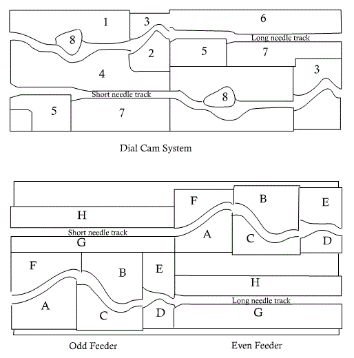
    Interlock cam system:
    In the figure the cylinder and dial camming to produce one course of ordinary interlock fabric which is actually work of two knitting feeders.

    The cylinder cam:

    A → clearing cam which lifts the needles to clear the old loop
    B, C → stitch cam and guard cams respectively both vertically adjustable to control the stitch length.
    D → up through to rise the needle whilst dial needle knock over
    E, F → guard cam to complete the truck
    G, H → guide cam to provide the track for idling needles
     

    Cylinder Cam System
    The dial system:
    1. Raising cam for tuck position only
    2, 3. Dial knock over cam
    4. Guard cam to compete the truck
    5. Auxiliary knock over cam to prevent the dial needle reentering the old loop
    6, 7 Guide cams provides the tracks for idling needles
    8. Sewing type clearing cam which may occupy the knitting position as shown in feeder 1 or in tuck position at feeder 2.

    Machine parts:

    1.  Yarn career 
    2.  Break stop motion 
    3.  Yarn guides 
    4.  Dial 
    5.  Cylinder 
    6.  Dial cams 
    7.  Cylinder cams 
    8.  Dial needles 
    9.  Cylinder needles 
    10.  Oiling and air following devices 
    11.  Sensors 
    12.  Take up rollers 
    13.  Batch rollers 
    14.  Motor 
    15.  Belts 
    16.  Pulleys and gears  Clutches
    Knitting action: 

    Conclusion:
    The circular Interlock machine is a very commonly used machine in country to make Interlock knitted fabric. So this experiment has significance in our study life. In this experiment we sketch the yarn path diagram of the machine, show the knitting action, cam system. We point out the various specification of the machine. So the experiment helps us to know more.

    Above all the experiment is a successful one.

    Interlock Circular Knitting Machine | Knitting Action of InterlockCircular Knitting Machine

    Posted at  04:28  |  in  regular  |  Continue lendo ...»

    Name of the Experiment: Study on interlock circular knitting machine.

    OBJECTS:
    1.To have the idea about an interlock m/c .
    2.To know about its working principles.

    Introduction:
    Interlock structure is a double faced Interlock structure which consists of two 1×1 Interlock structures. These two 1×1 Interlock structures are joined by interlocking sinker loops and thus produce interlock structure. Interlock structure is produce by special cylinder dial circular machines. Double system V-bed flat knitting machine also used to produce interlock structure.

    SPECIFICATIONS:

    1. Machine name: Interlock Circular Knitting Machine.
    2. Company:- Precision FUKUHARA Works Limited.
    3. Origin of the machine:- Japan
    4. Model no. :- V 8ME 42 
    5. Dia of the machine:- 30”.
    6. Gauge of the machine:- 22 
    7. No of Feeder:- 84 
    8. Serial no:- 1352761.
    9. Creel Capacity: 84.
    10. Feeding: Positive.
    MACHINE PARTS:
    1.Yarn career
    2.Break stop motion
    3.Yarn guides
    4.Dial
    5.Cylinder
    6.Dial cams
    7.Cylinder cams
    8.Dial needles
    9.Cylinder needles
    10.Oiling and air following devices
    11.Sensors
    12.Take up rollers
    13.Batch rollers
    14.Motor
    15.Belts 16.Clutches
    17.Pulleys and gears

    Machine description:
    The machine has two sets of needles on two different beds, one set on cylinder one in the dial bed. These two sets of needles must be exactly opposite to each other.

    The machine has two separate cam system in each bed needles of different length called short needles and long needles. Each cam system controls half of the needles in alternate sequences. One cam system controls knitting at one feeder and other ca, system controls at the next feeders. T ale down mechanism is the same as the other Interlock and plain machines mechanism.

    Interlock cam system:
    In the figure the cylinder and dial camming to produce one course of ordinary interlock fabric which is actually work of two knitting feeders.

    The cylinder cam:

    A → clearing cam which lifts the needles to clear the old loop
    B, C → stitch cam and guard cams respectively both vertically adjustable to control the stitch length.
    D → up through to rise the needle whilst dial needle knock over
    E, F → guard cam to complete the truck
    G, H → guide cam to provide the track for idling needles
     

    Cylinder Cam System
    The dial system:
    1. Raising cam for tuck position only
    2, 3. Dial knock over cam
    4. Guard cam to compete the truck
    5. Auxiliary knock over cam to prevent the dial needle reentering the old loop
    6, 7 Guide cams provides the tracks for idling needles
    8. Sewing type clearing cam which may occupy the knitting position as shown in feeder 1 or in tuck position at feeder 2.

    Machine parts:

    1.  Yarn career 
    2.  Break stop motion 
    3.  Yarn guides 
    4.  Dial 
    5.  Cylinder 
    6.  Dial cams 
    7.  Cylinder cams 
    8.  Dial needles 
    9.  Cylinder needles 
    10.  Oiling and air following devices 
    11.  Sensors 
    12.  Take up rollers 
    13.  Batch rollers 
    14.  Motor 
    15.  Belts 
    16.  Pulleys and gears  Clutches
    Knitting action: 

    Conclusion:
    The circular Interlock machine is a very commonly used machine in country to make Interlock knitted fabric. So this experiment has significance in our study life. In this experiment we sketch the yarn path diagram of the machine, show the knitting action, cam system. We point out the various specification of the machine. So the experiment helps us to know more.

    Above all the experiment is a successful one.

    Experiment Name: Study on knitting action of Tricot warp knitting machine.

    Introduction:
    The warp knitting machine is a knitting m/c where the loops are formed in course wise direction and the fabric produced is in open width form. In Tricot warp knitting m/c compound needles are used. The warp yarns are feed to the needles through guide bars using shogging and swinging motion.

    M/C specification:

    1. Brand: LIBA
    2. Origin: W. Germany
    3. Manufacturing Company: MASCHINEN FABRIK, NAILA.
    4. Manufacturing Year: 1991 
    5. Width: 84 inch/ 213 cm
    6. Type: COP 2K
    7. Gauge: 28 
    Knitting Action:
    1. The rest position: Te needles have risen to 2/3 of their full height from knock-over and have their hooks towards the back of the m/c. The latch bar is in downward position and the guides are at the front of the m/c with the sinkers forward, holding the old overlaps in their throats so that they are maintained in the correct height on the needle stems.

    2. Needle rise and guide bar swing: With the sinkers forward holding down the fabric, the hooks and tongues rise, with the hook rising faster, until the head of the latter is level with the guide holes and is open. The guides then swing through to the back of the m/c.

    3. The overlap and return swing: The guide’s shog for the overlap and swing to the front of the m/c immediately. The hooks and the tongues start to descend with the tongues descending more slowly, thus closing the hook.

    4. Hook closing: The hooks and the tongues start to descend with the tongues descending more slowly, thus closing the hook

    5. Landing:
    The sinkers start to withdraw as the needles descend so that the old loop is landed onto the closed hook. Thus the landing is occurred.

    6. Knock-over and under lap: The sinkers start to withdraw as the needles descend so that the old loop is landed onto the closed hook and then knocked over as it descends below the sinker belly. At this point the under lap occurs before the needles begin their upward rise and sinker move forward to hold down the fabric.

    7. The sinkers now move forward to hold down the fabric loops and push them away from the ascending needles, which are rising to the rest position.

    Conclusion:
    The knitting action of the Tricot warp knitting m/c is done by the needles, its sliding latches and the guide bars. The main work of feeding the thread around the needle is done by guides with their shogging and swinging motions. By this experiment I learned about the knitting action of a tricot warp knitting machine. This experience will help me in my future practical life.

    Knitting Action of Tricot Warp Knitting Machine

    Posted at  03:56  |  in  Warp Knitting  |  Continue lendo ...»

    Experiment Name: Study on knitting action of Tricot warp knitting machine.

    Introduction:
    The warp knitting machine is a knitting m/c where the loops are formed in course wise direction and the fabric produced is in open width form. In Tricot warp knitting m/c compound needles are used. The warp yarns are feed to the needles through guide bars using shogging and swinging motion.

    M/C specification:

    1. Brand: LIBA
    2. Origin: W. Germany
    3. Manufacturing Company: MASCHINEN FABRIK, NAILA.
    4. Manufacturing Year: 1991 
    5. Width: 84 inch/ 213 cm
    6. Type: COP 2K
    7. Gauge: 28 
    Knitting Action:
    1. The rest position: Te needles have risen to 2/3 of their full height from knock-over and have their hooks towards the back of the m/c. The latch bar is in downward position and the guides are at the front of the m/c with the sinkers forward, holding the old overlaps in their throats so that they are maintained in the correct height on the needle stems.

    2. Needle rise and guide bar swing: With the sinkers forward holding down the fabric, the hooks and tongues rise, with the hook rising faster, until the head of the latter is level with the guide holes and is open. The guides then swing through to the back of the m/c.

    3. The overlap and return swing: The guide’s shog for the overlap and swing to the front of the m/c immediately. The hooks and the tongues start to descend with the tongues descending more slowly, thus closing the hook.

    4. Hook closing: The hooks and the tongues start to descend with the tongues descending more slowly, thus closing the hook

    5. Landing:
    The sinkers start to withdraw as the needles descend so that the old loop is landed onto the closed hook. Thus the landing is occurred.

    6. Knock-over and under lap: The sinkers start to withdraw as the needles descend so that the old loop is landed onto the closed hook and then knocked over as it descends below the sinker belly. At this point the under lap occurs before the needles begin their upward rise and sinker move forward to hold down the fabric.

    7. The sinkers now move forward to hold down the fabric loops and push them away from the ascending needles, which are rising to the rest position.

    Conclusion:
    The knitting action of the Tricot warp knitting m/c is done by the needles, its sliding latches and the guide bars. The main work of feeding the thread around the needle is done by guides with their shogging and swinging motions. By this experiment I learned about the knitting action of a tricot warp knitting machine. This experience will help me in my future practical life.

    Name of the experiment: Study on Rib Circular knitting machine. 

    Introduction
    The structure in which the face and back loop occurs along to the coarse successively but all the loops of a wale is same is called rib structure. The circular knitting machine which is used to produce the rib structures is known as rib machine.

    Machine specification:

    1. Machine model → cmoan
    2. Manufacturer → Paolo Orizio
    3. Made in → Italy
    4. No of feeders’ → 40 
    5. Cylinder diameter →20”
    6. Needle gauge → 18 / inch
    Machine parts:
    1.  Yarn career
    2.  Break stop motion
    3.  Yarn guides
    4.  Dial
    5.  Cylinder
    6.  Dial cams
    7.  Cylinder cams
    8.  Dial needles
    9.  Cylinder needles
    10.  Oiling and air following devices
    11.  Sensors
    12.  Take up rollers
    13.  Batch rollers
    14.  Motor
    15.  Belts
    16.  Pulleys and gears
    17.  Clutches
    Description of the machine:
    In a dial cylinder rib machine there is one set of needles on the circumference of the vertical cylinder and another set of needles on a horizontal dial. So two sets of needles remain at the right angle with each other. In dial cylinder machines the dial and cylinder rotates but the cam systems with the feeders remain stationary.

    The dial needles get its motion from its butt which is placed on the cam truck. This cam truck is formed by different cam placed on a cam plate.

    During the rotation of the cylinder, cylinder needles moves vertically and dial needles moves horizontally. Cylinder needles also get its motion from it. There is a cloth tale up roller which also rotates with unison to dial and cylinder and fabric is wound on it. 

    In rib circular knitting m/c, Rib gaiting:

     Knitting action:
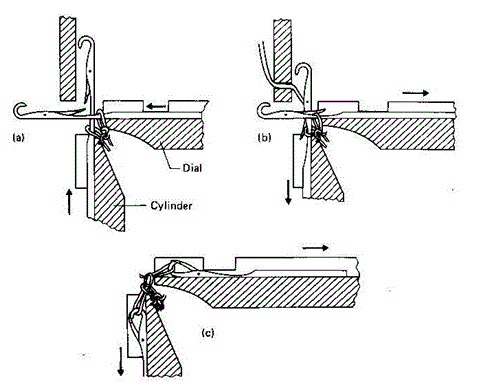
    The knitting action of a circular rib machine is shown in Fig:

    1. Clearing: The cylinder and dial needles move out to clear the plain and rib loops formed in the previous cycle.

    2. Yarn feeding: The needles are withdrawn into their tricks so that the old loops are covered by the open latches and the new yarn is fed into the open hooks.

    3. Knocking Over: The needles are withdrawn into their tricks so that the old loops are cast off and new loops are drawn through them.
     

    Fig: Knitting action of rib circular knitting machine
    Conclusion:
    This experiment has significance in our study life. In this experiment we sketch the yarn path diagram of the machine, show the knitting action, cam system. We point out the various specification of the machine.

    Rib Circular Knitting Machine

    Posted at  03:32  |  in  regular  |  Continue lendo ...»

    Name of the experiment: Study on Rib Circular knitting machine. 

    Introduction
    The structure in which the face and back loop occurs along to the coarse successively but all the loops of a wale is same is called rib structure. The circular knitting machine which is used to produce the rib structures is known as rib machine.

    Machine specification:

    1. Machine model → cmoan
    2. Manufacturer → Paolo Orizio
    3. Made in → Italy
    4. No of feeders’ → 40 
    5. Cylinder diameter →20”
    6. Needle gauge → 18 / inch
    Machine parts:
    1.  Yarn career
    2.  Break stop motion
    3.  Yarn guides
    4.  Dial
    5.  Cylinder
    6.  Dial cams
    7.  Cylinder cams
    8.  Dial needles
    9.  Cylinder needles
    10.  Oiling and air following devices
    11.  Sensors
    12.  Take up rollers
    13.  Batch rollers
    14.  Motor
    15.  Belts
    16.  Pulleys and gears
    17.  Clutches
    Description of the machine:
    In a dial cylinder rib machine there is one set of needles on the circumference of the vertical cylinder and another set of needles on a horizontal dial. So two sets of needles remain at the right angle with each other. In dial cylinder machines the dial and cylinder rotates but the cam systems with the feeders remain stationary.

    The dial needles get its motion from its butt which is placed on the cam truck. This cam truck is formed by different cam placed on a cam plate.

    During the rotation of the cylinder, cylinder needles moves vertically and dial needles moves horizontally. Cylinder needles also get its motion from it. There is a cloth tale up roller which also rotates with unison to dial and cylinder and fabric is wound on it. 

    In rib circular knitting m/c, Rib gaiting:

     Knitting action:
    The knitting action of a circular rib machine is shown in Fig:

    1. Clearing: The cylinder and dial needles move out to clear the plain and rib loops formed in the previous cycle.

    2. Yarn feeding: The needles are withdrawn into their tricks so that the old loops are covered by the open latches and the new yarn is fed into the open hooks.

    3. Knocking Over: The needles are withdrawn into their tricks so that the old loops are cast off and new loops are drawn through them.
     

    Fig: Knitting action of rib circular knitting machine
    Conclusion:
    This experiment has significance in our study life. In this experiment we sketch the yarn path diagram of the machine, show the knitting action, cam system. We point out the various specification of the machine.

    Super Ofertas

    --
    Copyright © 2013 fibres2fashion. Blogger Template by BloggerTheme9
    Proudly Powered by Blogger.
    back to top