• Em Destaque

    Aqui Você Encontra Os Melhores Template da Internet .

  • Em Destaque

    Aqui Você Encontra Os Melhores Template da Internet .

  • Em Destaque

    Aqui Você Encontra Os Melhores Template da Internet .

  • Em Destaque

    Aqui Você Encontra Os Melhores Template da Internet .

  • Curte aí!

    Showing posts with label Spinning M/C. Show all posts
    Showing posts with label Spinning M/C. Show all posts

    Tuesday, 21 February 2012

    In normal concept ”Engineering” means gathering of different kinds of machines . In case of textile engineering process also needs different kinds of machines to produce finished products means garments from fiber.

    List of Textile Machineries are used in Textile Manufacturing Process:

    In case of Fiber Preparation or Ginning:

    Ginning Machines:

    1. Saw ginning machine
    2. Knife Roller ginning machine
    3. Mecharthy ginning machine

    Machineries List of Yarn Spinning:

    1. Hopper bale opener or Bale plucker

    2. Step clener or Ultra cleaner or Super cleaner
    3. Verticle / Twine opener or cleaner
    4. Hopper feeder
    5. Porcupine opener
    6. Kirschner beater
    7. Cotton cleaner
    8. R.N. beater
    9. S.R.R.L. beater
    10. Mono cylinder beater
    11. Scutcher
    12. Carding machine
    13. Drawing Frame
    14. Lap former
    15. Comber machine
    16. Simplex
    17. Ring Frame
    18. Cone winding machine/Auto coner 
    Machineries are Used in Jute Spinning:

    1. Jute 1st draw frame machine
    2. Jute 2nd draw frame machine
    3. Jute 3rd draw frame machine
    4. Jute Slip Draft Spinning frame
    5. Jute Apron Draft Spinning Frame Machine

    6. Breaker Carding machine
    7. Finisher Carding machine

    List of Textile Machineries are Used in Textile Manufacturing Process |Yarn Spinning Machines

    Posted at  04:06  |  in  Spinning M/C  |  Continue lendo ...»

    In normal concept ”Engineering” means gathering of different kinds of machines . In case of textile engineering process also needs different kinds of machines to produce finished products means garments from fiber.

    List of Textile Machineries are used in Textile Manufacturing Process:

    In case of Fiber Preparation or Ginning:

    Ginning Machines:

    1. Saw ginning machine
    2. Knife Roller ginning machine
    3. Mecharthy ginning machine

    Machineries List of Yarn Spinning:

    1. Hopper bale opener or Bale plucker

    2. Step clener or Ultra cleaner or Super cleaner
    3. Verticle / Twine opener or cleaner
    4. Hopper feeder
    5. Porcupine opener
    6. Kirschner beater
    7. Cotton cleaner
    8. R.N. beater
    9. S.R.R.L. beater
    10. Mono cylinder beater
    11. Scutcher
    12. Carding machine
    13. Drawing Frame
    14. Lap former
    15. Comber machine
    16. Simplex
    17. Ring Frame
    18. Cone winding machine/Auto coner 
    Machineries are Used in Jute Spinning:

    1. Jute 1st draw frame machine
    2. Jute 2nd draw frame machine
    3. Jute 3rd draw frame machine
    4. Jute Slip Draft Spinning frame
    5. Jute Apron Draft Spinning Frame Machine

    6. Breaker Carding machine
    7. Finisher Carding machine

    Saturday, 18 February 2012

    Crighton Opener
    Crighton opener


    Crighton opener machine is used to open cotton tuft in blowroom line. It is also called Verticle Opener Machine or Twine Opener Machine

    Object Crighton Opener:
    i. To strike the cotton while it is being carried by the air current.
    ii. To open the cotton in to small fault.
    iii. To use low quality cotton (i.e. cotton of short staple & more impurities).


    Main Parts of Crighton Opener M/C :
    i. Motor.
    ii. Motor pulley
    iii. Discs with strikes.
    iv. Inclines Grid bar.

    Adjustment of Different Parts :

    1. Grid bar to grid bar :
    Wider setting: High fiber loss, poor opening & cleaning, high speed, high productions.
    Closer setting: Good opening, low speed gives lower fiber loss & low production.

    2. Blade to grid bar :
    Wider Setting: No fiber damage, high production, poor opening & cleaning.
    Closer setting: Fiber damage, low production, lower removal of impurities, good opening.

    Specification Crighton Opener M/C  :
    i. Motor r.p.m = 1440
    ii. Motor pulley dia = 14“
    iii. M/C pulley dia = 32“
    iv. No. of striker = 6


    Calculation :
    Beater r.p.m = 1440*(14“/32“) = 630
    Beats per min = 630*6 = 3780

    Conclusion :
    This is the third m/c of the blowroom line. It stands on a vertical shaft & hence it is called vertical opener. This m/c is a major cleaning point of blow room line. There is a by pass system. So from step cleaner cotton can be difficulty pass to the hopper feeder without vertical opener. It can be used in case of low grade cotton. For beater opening & cleaning close setting of striker is done. But there is a rise of more fiber damage. Hence moderate setting is done.

    Crighton Opener Machine/Verticle Opener Machine/Twine Opener Machine |Main Parts of Crighton Opener M/C

    Posted at  13:34  |  in  Spinning M/C  |  Continue lendo ...»

    Crighton Opener
    Crighton opener


    Crighton opener machine is used to open cotton tuft in blowroom line. It is also called Verticle Opener Machine or Twine Opener Machine

    Object Crighton Opener:
    i. To strike the cotton while it is being carried by the air current.
    ii. To open the cotton in to small fault.
    iii. To use low quality cotton (i.e. cotton of short staple & more impurities).


    Main Parts of Crighton Opener M/C :
    i. Motor.
    ii. Motor pulley
    iii. Discs with strikes.
    iv. Inclines Grid bar.

    Adjustment of Different Parts :

    1. Grid bar to grid bar :
    Wider setting: High fiber loss, poor opening & cleaning, high speed, high productions.
    Closer setting: Good opening, low speed gives lower fiber loss & low production.

    2. Blade to grid bar :
    Wider Setting: No fiber damage, high production, poor opening & cleaning.
    Closer setting: Fiber damage, low production, lower removal of impurities, good opening.

    Specification Crighton Opener M/C  :
    i. Motor r.p.m = 1440
    ii. Motor pulley dia = 14“
    iii. M/C pulley dia = 32“
    iv. No. of striker = 6


    Calculation :
    Beater r.p.m = 1440*(14“/32“) = 630
    Beats per min = 630*6 = 3780

    Conclusion :
    This is the third m/c of the blowroom line. It stands on a vertical shaft & hence it is called vertical opener. This m/c is a major cleaning point of blow room line. There is a by pass system. So from step cleaner cotton can be difficulty pass to the hopper feeder without vertical opener. It can be used in case of low grade cotton. For beater opening & cleaning close setting of striker is done. But there is a rise of more fiber damage. Hence moderate setting is done.

    Tuesday, 14 February 2012

    Experiment name: Gearing diagram and calculations of feed/nip, nips/min, brush speed, production, draft, draft constant of the comber machine.

    Objects:

    i) To observe nipper movement.
    ii) To know about drafting system.
    iii) To know about speed of brush, cylinder, and lap feed roller, detaching roller.
    iv) To find draft and draft constant.

    Specification of the machine:
    • Main motor RPM = 1395 
    • Diameter of main motor pulley= 167mm
    • Brush motor RPM = 2860 
    • Diameter of brush motor pulley = 243mm
    • Diameter of cylinder = 125mm
    • Diameter of brush roller = 110mm
    • Diameter of feed roller = 70mm
    • Diameter of back roller = 30mm
    • Diameter of middle roller =30mm
    • Diameter of front roller = 40mm
    • DCP = 78T
    Calculation:


    Results:

    i) Brush speed =961.38 rpm.
    ii) Nips/min= 215.72 rpm.
    iii) Feed/nip= 4.48 mm.
    iv) Break draft = 1.27 
    v) Total draft = 10.89

    vi) Draft constant = 849.42 
    vii) Production/machine/ shift in lbs= 394.48 lbs.

    Conclusions:

    Comber M/C is very important & necessary M/C of producing combed sliver. This experiment is very helpful for us to learn about this M/C. So, we should learn about this experiment very carefully. Especial thanks to our teacher and his assistant for helping us.


    Draft and Draft Constant of the Comber Machine | Gearing Diagram of Comber Machine

    Posted at  02:01  |  in  Spinning M/C  |  Continue lendo ...»

    Experiment name: Gearing diagram and calculations of feed/nip, nips/min, brush speed, production, draft, draft constant of the comber machine.

    Objects:

    i) To observe nipper movement.
    ii) To know about drafting system.
    iii) To know about speed of brush, cylinder, and lap feed roller, detaching roller.
    iv) To find draft and draft constant.

    Specification of the machine:
    • Main motor RPM = 1395 
    • Diameter of main motor pulley= 167mm
    • Brush motor RPM = 2860 
    • Diameter of brush motor pulley = 243mm
    • Diameter of cylinder = 125mm
    • Diameter of brush roller = 110mm
    • Diameter of feed roller = 70mm
    • Diameter of back roller = 30mm
    • Diameter of middle roller =30mm
    • Diameter of front roller = 40mm
    • DCP = 78T
    Calculation:


    Results:

    i) Brush speed =961.38 rpm.
    ii) Nips/min= 215.72 rpm.
    iii) Feed/nip= 4.48 mm.
    iv) Break draft = 1.27 
    v) Total draft = 10.89

    vi) Draft constant = 849.42 
    vii) Production/machine/ shift in lbs= 394.48 lbs.

    Conclusions:

    Comber M/C is very important & necessary M/C of producing combed sliver. This experiment is very helpful for us to learn about this M/C. So, we should learn about this experiment very carefully. Especial thanks to our teacher and his assistant for helping us.


    Name of experiment: Study on the material passage of Comber machine.

    Objects:

    1) To remove fibres shorter tan a predetermined length so as to enable spinner to produce finer yarn than that can be spun from the same carded sliver.
    2) To remove neps and impurities.
    3) To produce uniform sliver of required wt/unit length.
    4) To make the fibre straight and parallel so that yarn become even and lustrous.

    Machine specification:


    • Brand name: LAKSHMI
    • Model no: LK250 
    • Mfg. country: INDIA
    Main parts:
    1) Lap r/r
    2) Tension r/r
    3) Condenser.
    4) Feed r/r
    5) Top nipper.
    6) Bottom nipper.
    7) Top comb
    8) Bottom comb
    9) Detaching r/r
    10) Condenser.
    11) Table.
    12) Drafting r/r
    13) Cloth cleaner.
    14) Belt
    15) Trumpet
    16) Calendar r/r
    17) Coiler calendar r/r
    18) Coiler head
    19) Can

    Passage diagram:

    At first lap is fed by lap roller. Then lap is passed though the condenser. Material is passed under the feed roller and through the nipper. Here top and bottom nippers are used to nip the lap. Then lap is passed through the detaching roller. Here a cloth clearer is used to clean the lap. Then it passes through the condenser and calendar roller. Then it enters into the drafting zone by the feed table. Then the drafted material is passed by the help of belt into trumpet. Finally it is deposited into can by passing though coiler calendar roller and coiler head.

    Conclusion:

    This practical is one of the most important practical for spinning section. By this practical we learn about different parts & material passage of comber machine.

    Comber Machine | Study on the Material Passage of Comber machine

    Posted at  00:43  |  in  Spinning M/C  |  Continue lendo ...»

    Name of experiment: Study on the material passage of Comber machine.

    Objects:

    1) To remove fibres shorter tan a predetermined length so as to enable spinner to produce finer yarn than that can be spun from the same carded sliver.
    2) To remove neps and impurities.
    3) To produce uniform sliver of required wt/unit length.
    4) To make the fibre straight and parallel so that yarn become even and lustrous.

    Machine specification:


    • Brand name: LAKSHMI
    • Model no: LK250 
    • Mfg. country: INDIA
    Main parts:
    1) Lap r/r
    2) Tension r/r
    3) Condenser.
    4) Feed r/r
    5) Top nipper.
    6) Bottom nipper.
    7) Top comb
    8) Bottom comb
    9) Detaching r/r
    10) Condenser.
    11) Table.
    12) Drafting r/r
    13) Cloth cleaner.
    14) Belt
    15) Trumpet
    16) Calendar r/r
    17) Coiler calendar r/r
    18) Coiler head
    19) Can

    Passage diagram:

    At first lap is fed by lap roller. Then lap is passed though the condenser. Material is passed under the feed roller and through the nipper. Here top and bottom nippers are used to nip the lap. Then lap is passed through the detaching roller. Here a cloth clearer is used to clean the lap. Then it passes through the condenser and calendar roller. Then it enters into the drafting zone by the feed table. Then the drafted material is passed by the help of belt into trumpet. Finally it is deposited into can by passing though coiler calendar roller and coiler head.

    Conclusion:

    This practical is one of the most important practical for spinning section. By this practical we learn about different parts & material passage of comber machine.

    Monday, 13 February 2012

    Experiment Name: Study on ring doubling frame
    1.Spindle speed, front roller delivery.
    2.Twist, twist Constant.

    Objects:

    1) To combine two or more single threads into one.
    2) To insert sufficient amount of twist for holding the yarns.
    3) To increase strength, smoothness and luster.
    4) To reduce hairiness.
    5) To make sewing thread.
    6) To wind a suitable bobbin.

    Main parts:  
    1. Creel stand and creel. 
    2. Front roller. 
    3. Yarn guide. 
    4. Ring and ring rail  
    5. Tin cylinder. 
    6. Traveller.  
    7. Thread weight or slip roller. 
    8.  Lappet  Spindle.
    Specification:
    • Motor rpm = 1430 
    • Motor pulley diameter = 6.25²
    • Machine pulley diameter = 10.25²
    • Tin cylinder diameter = 10²
    • Wharve diameter = 1.37²
    • Cylinder carrier wheel = 24T
    • TCP carrier wheel = 62T
    • TCP = 63T
    • Front roller diameter = 2’’
    Calculation:
    Gearing diagram of doubling frame: 
     

    Figure: gearing diagram of doubling frame.
    Result:
    1) Spindle speed = 6461.59 rpm
    2) Twist constant = 1235.25
    3) Front roller delivery = 319.143 inch/min.
    4) Existing TPI =
    20
    5) Production = 14.37 lb/shift/frame.
    6) Required TPI = 16.266

    7) Required TCP =76.25T

    Conclusion: 
    By this experiment we come to know about various parts and working principle of ring doubling frame. This machine is important for producing double yarn on sewing thread.

    Doubling in Ring Frame | Study on Ring Doubling Frame

    Posted at  23:49  |  in  Twist  |  Continue lendo ...»

    Experiment Name: Study on ring doubling frame
    1.Spindle speed, front roller delivery.
    2.Twist, twist Constant.

    Objects:

    1) To combine two or more single threads into one.
    2) To insert sufficient amount of twist for holding the yarns.
    3) To increase strength, smoothness and luster.
    4) To reduce hairiness.
    5) To make sewing thread.
    6) To wind a suitable bobbin.

    Main parts:  
    1. Creel stand and creel. 
    2. Front roller. 
    3. Yarn guide. 
    4. Ring and ring rail  
    5. Tin cylinder. 
    6. Traveller.  
    7. Thread weight or slip roller. 
    8.  Lappet  Spindle.
    Specification:
    • Motor rpm = 1430 
    • Motor pulley diameter = 6.25²
    • Machine pulley diameter = 10.25²
    • Tin cylinder diameter = 10²
    • Wharve diameter = 1.37²
    • Cylinder carrier wheel = 24T
    • TCP carrier wheel = 62T
    • TCP = 63T
    • Front roller diameter = 2’’
    Calculation:
    Gearing diagram of doubling frame: 
     

    Figure: gearing diagram of doubling frame.
    Result:
    1) Spindle speed = 6461.59 rpm
    2) Twist constant = 1235.25
    3) Front roller delivery = 319.143 inch/min.
    4) Existing TPI =
    20
    5) Production = 14.37 lb/shift/frame.
    6) Required TPI = 16.266

    7) Required TCP =76.25T

    Conclusion: 
    By this experiment we come to know about various parts and working principle of ring doubling frame. This machine is important for producing double yarn on sewing thread.

    Experiment name: Study on the gearing diagram, calculation of spindle speed and front roller speed of the ring frame.

    Object:

    1. To know about the different parts of the ring frame.
    2. To know about the function of the different parts of the ring frame machine.
    3. To know about the driving mechanism of the spindle
    4. To calculate the front roller delivery of the machine
    5. To study the machine in order to improve our technical knowledge.

    Gearing Diagram
    Ring Frame:
    Fig: Gearing diagram of ring frame
    Machine specification:
    • RPM of the motor = 1440 
    • Diameter of the motor pulley = 5″
    • Diameter of the tin cylinder pulley = 10.5″
    • Diameter of the tin cylinder = 10″
    • Diameter of the wharve = 1.125″
    • No of teeth of lower grip wheel = 26T
    • No of teeth of upper grip wheel = 46T
    • No of teeth of fibre wheel = 42T
    • No of teeth of twist carrier wheel = 86T
    • No of teeth of twist wheel = 48T
    • No of teeth of front roller driving wheel = 98T
    • Diameter of front roller = 1″
    Calculation:

    Result:
    Spindle Speed = 6095.24 rpm
    Front roller delivery = 323.56 inch/min

    Conclusion:

    Our teacher and lab assistants are very much helpful to us. Their well teaching and instruction help us greatly to understand this practical. I think this practical will be very helpful in my future career.


    Calculation of Spindle Speed and Front Roller Speed of the Ring Frame | Gearing Diagram of Ring Frame

    Posted at  22:36  |  in  Spinning M/C  |  Continue lendo ...»

    Experiment name: Study on the gearing diagram, calculation of spindle speed and front roller speed of the ring frame.

    Object:

    1. To know about the different parts of the ring frame.
    2. To know about the function of the different parts of the ring frame machine.
    3. To know about the driving mechanism of the spindle
    4. To calculate the front roller delivery of the machine
    5. To study the machine in order to improve our technical knowledge.

    Gearing Diagram
    Ring Frame:
    Fig: Gearing diagram of ring frame
    Machine specification:
    • RPM of the motor = 1440 
    • Diameter of the motor pulley = 5″
    • Diameter of the tin cylinder pulley = 10.5″
    • Diameter of the tin cylinder = 10″
    • Diameter of the wharve = 1.125″
    • No of teeth of lower grip wheel = 26T
    • No of teeth of upper grip wheel = 46T
    • No of teeth of fibre wheel = 42T
    • No of teeth of twist carrier wheel = 86T
    • No of teeth of twist wheel = 48T
    • No of teeth of front roller driving wheel = 98T
    • Diameter of front roller = 1″
    Calculation:

    Result:
    Spindle Speed = 6095.24 rpm
    Front roller delivery = 323.56 inch/min

    Conclusion:

    Our teacher and lab assistants are very much helpful to us. Their well teaching and instruction help us greatly to understand this practical. I think this practical will be very helpful in my future career.


    Experiment name: Study on the material passage of Ring frame.

    Object:
    1. To produce required count of yarn from the supplied roving by the drafting.

    2. To insert sufficient amount of twist to the yarn.
    3. To wind the yarn onto the bobbin.
    4. To build the yarn package properly.

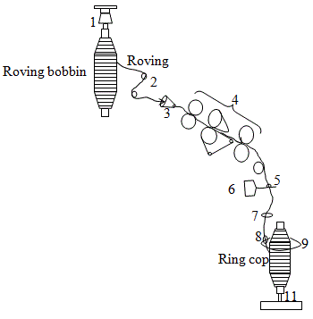
    Main Parts Ring Frame:

    1. Creel

    2. Guide roller
    3. Trumpet
    4. Drafting rollers
    5. Yarn guide
    6. Lappet
    7. Balloon controlling ring
    8. Traveler
    9. Ring
    10. Spindle

    Specification:

    I. Name of manufacturer: Platts.
    II. No of spindle: 64 
    III. Ring dia: 6.2 cm
    IV. Lift of the bobbin: 9”

    Passage diagram:
    Fig: Passage Diagram of Ring frame
    Description:
    The feed material come from speed frame i.e. roving bobbin is placed on the creel. The creel which is attached to the machine is umbrella type. Then feed material is passed under the guide rollers and through the trumpet in to the drafting zone. Here some draft is inserted in to the roving. The draft system is 3 over 3 drafting system with apron. The delivery material that is delivered from the front roller is reached to the traveler over pneumatic waste collector, lappet and through balloon controlling ring. Lappet is used to control the material path and balloon controlling ring is used to control the balloon formation and spinning tension. Here roving is twisted by the movement of the traveler around the ring. The yarn is then wound on the ring cop.

    Conclusion:

    Our teacher and lab assistants are very much helpful to us. Their well teaching and instruction help us greatly to understand this practical. I think this practical will be very helpful in my future career.


    Ring Frame | Material Passage Diagram of Ring Frame

    Posted at  21:07  |  in  Spinning M/C  |  Continue lendo ...»

    Experiment name: Study on the material passage of Ring frame.

    Object:
    1. To produce required count of yarn from the supplied roving by the drafting.

    2. To insert sufficient amount of twist to the yarn.
    3. To wind the yarn onto the bobbin.
    4. To build the yarn package properly.

    Main Parts Ring Frame:

    1. Creel

    2. Guide roller
    3. Trumpet
    4. Drafting rollers
    5. Yarn guide
    6. Lappet
    7. Balloon controlling ring
    8. Traveler
    9. Ring
    10. Spindle

    Specification:

    I. Name of manufacturer: Platts.
    II. No of spindle: 64 
    III. Ring dia: 6.2 cm
    IV. Lift of the bobbin: 9”

    Passage diagram:
    Fig: Passage Diagram of Ring frame
    Description:
    The feed material come from speed frame i.e. roving bobbin is placed on the creel. The creel which is attached to the machine is umbrella type. Then feed material is passed under the guide rollers and through the trumpet in to the drafting zone. Here some draft is inserted in to the roving. The draft system is 3 over 3 drafting system with apron. The delivery material that is delivered from the front roller is reached to the traveler over pneumatic waste collector, lappet and through balloon controlling ring. Lappet is used to control the material path and balloon controlling ring is used to control the balloon formation and spinning tension. Here roving is twisted by the movement of the traveler around the ring. The yarn is then wound on the ring cop.

    Conclusion:

    Our teacher and lab assistants are very much helpful to us. Their well teaching and instruction help us greatly to understand this practical. I think this practical will be very helpful in my future career.


    Name of the experiment: Study on the building mechanism of speed frame.

    Objects:

    1. To provide reversing motion of the bobbin rail.
    2. To transfer the cone drum belt so that bobbin speed is decreased with the increase of bobbin dia.
    3. To make the tapering shape pf the bobbin.

    Function of building mechanism:

    1) To transfer the cone drum belt.
    2) To traverse the bobbin rail.

    1) To transfer the cone drum belt:
    This mechanism consists of following machine parts.
    i) Dead wt.
    ii) Rack driving wheel.
    iii) Rack
    iv) Vertical shaft.
    v) Connecting rod.
    vi) Connecting bar.
    vii) Ratchet wheel.

    There is a dead wt. at one end of the mechanism which causes the vertical shaft to rotate. They are connected through a chain. There is a rack driving wheel connected to the vertical shaft. The rack is behind the rack driving wheel. The motion of vertical shaft causes the rack driving wheel to rotate. If rack wheel rotate in the clockwise direction, it cause the rack to move in the left side. The be of cone drum is connected with the rack through a connecting rod. The left side movement of rack causes the belt to move to the left, thus reducing bobbin speed with its increasing dia.

    The rack driving wheel moves in the anticlockwise direction then rack will move to the right causes the belt to move to the right. The rotation of vertical shaft is controlled by ratchet wheel. The movement of vertical shaft may be continuous due to dead weight. But ratchet wheel controls its movement. The ratchet wheel makes a 0.5 inch movement after completing winding of one layer of roving on the bobbin. As vertical shaft is connected with ratchet wheel it cannot move continuously. Again the amount of shifting of belt depends upon roving thickness i.e. on roving count. The amount of shifting of belt is controlled by replacement of ratchet wheel on by substitution of change wheels. When the bobbin is fully wound the belt must be moved back to its starting point. Today it is usually done automatically.

    2) To traverse the bobbin rail:

    Second function of the building mechanism is to traverse the bobbin rail. If the bobbin does not traverse the roving will wind in only one position thus making the package unstable. So to wind roving on to full length of bobbin it requires traversing motion of bobbin rail. It is done by the above mechanism. 
     
    In this mechanism the following parts are available.
    a. Rack driving wheel.
    b. Rack
    c. Lifter change pinion.
    d. Double bevel.
    e. Fixed bevel.
    f. Bobbin rail driving shaft.
    g. Connecting rod.

    The connecting rod gets traversing motion from building mechanism. Double bevel is on the connecting rod. During the motion of the connecting rod when the left bevel comes in contact with the fixed bevel it gets motion from the fixed bevel. The fixed bevel has a definite direction of movement. If it moves in anti clockwise direction the left bevel will move in clockwise direction. Through gear train bobbin rail driving shaft will also move in clockwise direction. The rack driving

    Wheel which is on it will also move in clockwise direction. Thus causing the rack to move in downward direction. Again when right bevel comes in contact with fixed bevel it will move in anti-clock wise direction. Through gear train the bobbin rail driving shaft will also move in anti-clock wise direction. So the rack will move in upward direction. In this way traversing of bobbin rail occurred.

    Conclusion:

    The function of building mechanism of the speed frame is to transfer the cone drum belt and to traverse the bobbin rail. By this practical we learn about the building mechanism of speed frame practically. Special thanks to our teacher and his assistance for helping us.


    Building Mechanism of Speed Frame / Roving Frame / Simplex Machine

    Posted at  20:48  |  in  Spinning M/C  |  Continue lendo ...»

    Name of the experiment: Study on the building mechanism of speed frame.

    Objects:

    1. To provide reversing motion of the bobbin rail.
    2. To transfer the cone drum belt so that bobbin speed is decreased with the increase of bobbin dia.
    3. To make the tapering shape pf the bobbin.

    Function of building mechanism:

    1) To transfer the cone drum belt.
    2) To traverse the bobbin rail.

    1) To transfer the cone drum belt:
    This mechanism consists of following machine parts.
    i) Dead wt.
    ii) Rack driving wheel.
    iii) Rack
    iv) Vertical shaft.
    v) Connecting rod.
    vi) Connecting bar.
    vii) Ratchet wheel.

    There is a dead wt. at one end of the mechanism which causes the vertical shaft to rotate. They are connected through a chain. There is a rack driving wheel connected to the vertical shaft. The rack is behind the rack driving wheel. The motion of vertical shaft causes the rack driving wheel to rotate. If rack wheel rotate in the clockwise direction, it cause the rack to move in the left side. The be of cone drum is connected with the rack through a connecting rod. The left side movement of rack causes the belt to move to the left, thus reducing bobbin speed with its increasing dia.

    The rack driving wheel moves in the anticlockwise direction then rack will move to the right causes the belt to move to the right. The rotation of vertical shaft is controlled by ratchet wheel. The movement of vertical shaft may be continuous due to dead weight. But ratchet wheel controls its movement. The ratchet wheel makes a 0.5 inch movement after completing winding of one layer of roving on the bobbin. As vertical shaft is connected with ratchet wheel it cannot move continuously. Again the amount of shifting of belt depends upon roving thickness i.e. on roving count. The amount of shifting of belt is controlled by replacement of ratchet wheel on by substitution of change wheels. When the bobbin is fully wound the belt must be moved back to its starting point. Today it is usually done automatically.

    2) To traverse the bobbin rail:

    Second function of the building mechanism is to traverse the bobbin rail. If the bobbin does not traverse the roving will wind in only one position thus making the package unstable. So to wind roving on to full length of bobbin it requires traversing motion of bobbin rail. It is done by the above mechanism. 
     
    In this mechanism the following parts are available.
    a. Rack driving wheel.
    b. Rack
    c. Lifter change pinion.
    d. Double bevel.
    e. Fixed bevel.
    f. Bobbin rail driving shaft.
    g. Connecting rod.

    The connecting rod gets traversing motion from building mechanism. Double bevel is on the connecting rod. During the motion of the connecting rod when the left bevel comes in contact with the fixed bevel it gets motion from the fixed bevel. The fixed bevel has a definite direction of movement. If it moves in anti clockwise direction the left bevel will move in clockwise direction. Through gear train bobbin rail driving shaft will also move in clockwise direction. The rack driving

    Wheel which is on it will also move in clockwise direction. Thus causing the rack to move in downward direction. Again when right bevel comes in contact with fixed bevel it will move in anti-clock wise direction. Through gear train the bobbin rail driving shaft will also move in anti-clock wise direction. So the rack will move in upward direction. In this way traversing of bobbin rail occurred.

    Conclusion:

    The function of building mechanism of the speed frame is to transfer the cone drum belt and to traverse the bobbin rail. By this practical we learn about the building mechanism of speed frame practically. Special thanks to our teacher and his assistance for helping us.


    Experiment name: Calculation of no of coils per inch of the roving bobbin.

    Objects:
    1. To know the necessary specification for calculation.
    2. To know how to calculate the coils/inch of roving bobbin.

    Theory:


    M/c specification:

    1. Rpm of motor pulley = 960 
    2. Motor pulley diameter = 5″
    3. Machine pulley diameter = 7″
    4. Cradle wheel = 40T
    5. Cradle carrier wheel = 55 T
    6. No of teeth in TCP = 28T
    7. No of teeth in TCCP = 30T
    8. Diameter of top cone drum = 6.5″
    9. Diameter of bottom cone drum = 3.87″
    10. Bottom cone drum change wheel = 18T
    11. No of teeth of fender wheel = 68T
    12. No of teeth of fender shaft wheel = 30T
    13. Fender swivel bracket carrier wheel = 36T
    14. Top lifter change wheel = 18T
    15. Wheel on stud bevel = 44T
    16. Stud bevel wheel = 22T
    17. Double upright bevel wheel = 22T
    18. Double upright bevel wheel = 18T
    19. Reversing bevel = 70T
    20. Reversing bevel = 70T
    21. Bobbin lifter change pinion = 16T
    22. Socket swivel carrier wheel = 72T
    23. Socket stud wheel = 13T
    24. Differential motion carrier wheel = 57T
    Fig: Gearing diagram of Roving Frame to calculate no of coils per inch of the roving bobbin
    Calculation:
    We know, Bobbin speed = 822 

    Spindle speed = 749 
    Therefore, Coils per minute = 822 – 749 

                                              = 73 

    Result:
    No. of coils per inch = 11.

    Conclusion: 
    Our teacher and lab assistants are very much helpful to us. Their well teaching and instruction help us greatly to understand this practical. I think this practical will be very helpful in my future career.

    Calculation of no of Coils per inch of the Roving Bobbin

    Posted at  20:38  |  in  Spinning M/C  |  Continue lendo ...»

    Experiment name: Calculation of no of coils per inch of the roving bobbin.

    Objects:
    1. To know the necessary specification for calculation.
    2. To know how to calculate the coils/inch of roving bobbin.

    Theory:


    M/c specification:

    1. Rpm of motor pulley = 960 
    2. Motor pulley diameter = 5″
    3. Machine pulley diameter = 7″
    4. Cradle wheel = 40T
    5. Cradle carrier wheel = 55 T
    6. No of teeth in TCP = 28T
    7. No of teeth in TCCP = 30T
    8. Diameter of top cone drum = 6.5″
    9. Diameter of bottom cone drum = 3.87″
    10. Bottom cone drum change wheel = 18T
    11. No of teeth of fender wheel = 68T
    12. No of teeth of fender shaft wheel = 30T
    13. Fender swivel bracket carrier wheel = 36T
    14. Top lifter change wheel = 18T
    15. Wheel on stud bevel = 44T
    16. Stud bevel wheel = 22T
    17. Double upright bevel wheel = 22T
    18. Double upright bevel wheel = 18T
    19. Reversing bevel = 70T
    20. Reversing bevel = 70T
    21. Bobbin lifter change pinion = 16T
    22. Socket swivel carrier wheel = 72T
    23. Socket stud wheel = 13T
    24. Differential motion carrier wheel = 57T
    Fig: Gearing diagram of Roving Frame to calculate no of coils per inch of the roving bobbin
    Calculation:
    We know, Bobbin speed = 822 

    Spindle speed = 749 
    Therefore, Coils per minute = 822 – 749 

                                              = 73 

    Result:
    No. of coils per inch = 11.

    Conclusion: 
    Our teacher and lab assistants are very much helpful to us. Their well teaching and instruction help us greatly to understand this practical. I think this practical will be very helpful in my future career.

    Name of the experiment: Calculation of twist, twist constant of the speed frame machine.

    Introduction:

    Twist is the spiral turns given to a yarn to increase the strength of the yarn. But in speed frame machine vary small amount of twist is given to the roving to make it able to wound onto a bobbin. For a fibrous material twist is measured by the parameter twist per inch (TPI), twist per centimeter or twist per meter (TPM). For the cotton sample twist is measured by TPI.

    In speed frame machines twist per unit is varied with the variation of raw material and its different parameters. This variation of twist is inserted by changing a wheel that is connected with the main driving shaft named twist change pinion (TCP). And the multiply of TCP and TPI, present in a machine is called twist constant. This value is applicable for any required twist with corresponding TCP. So we can find out the required TCP to get a given TPI. The generalize formulae is as below: 


    Specification:
    • Front roller carrier wheel :80T(A)
    • Twist constant change pinion carrier:30T(B)
    • Twist constant change pinion:30T(C)
    • Twist change pinion:28T(D)
    • Sprocket wheel:34T(E)
    • Sprocket pinion:36T(F)
    • Spindle carrier wheel:40T(G)
    • Spindle wheel:22T(H)
    GEARING DIAGRAM:
    Fig: Gearing diagram of speed frame
    Calculation:
     
    Result:
    Twist per inch TPI → 1.56 
    Required TCP → 33 

    Conclusion:

    Speed frame is the first machine which enables the winding of the fibrous material on to a package. From this machine the fibre gets a circular shape which is very advantageous to be used in ring spinning. So the importance of this machine is very much. In this experiment we indicate different gearing diagram of the twist inserting portion; specify it and calculate twist and twist constant. We found a satisfactory result. So the experiment is a successful one.


    Twist Constant of the Speed Frame / Simplex M/C / Roving Frame Machine | Calculation of Twist, Twist Constant of the Speed Frame Machine

    Posted at  20:16  |  in  Twist  |  Continue lendo ...»

    Name of the experiment: Calculation of twist, twist constant of the speed frame machine.

    Introduction:

    Twist is the spiral turns given to a yarn to increase the strength of the yarn. But in speed frame machine vary small amount of twist is given to the roving to make it able to wound onto a bobbin. For a fibrous material twist is measured by the parameter twist per inch (TPI), twist per centimeter or twist per meter (TPM). For the cotton sample twist is measured by TPI.

    In speed frame machines twist per unit is varied with the variation of raw material and its different parameters. This variation of twist is inserted by changing a wheel that is connected with the main driving shaft named twist change pinion (TCP). And the multiply of TCP and TPI, present in a machine is called twist constant. This value is applicable for any required twist with corresponding TCP. So we can find out the required TCP to get a given TPI. The generalize formulae is as below: 


    Specification:
    • Front roller carrier wheel :80T(A)
    • Twist constant change pinion carrier:30T(B)
    • Twist constant change pinion:30T(C)
    • Twist change pinion:28T(D)
    • Sprocket wheel:34T(E)
    • Sprocket pinion:36T(F)
    • Spindle carrier wheel:40T(G)
    • Spindle wheel:22T(H)
    GEARING DIAGRAM:
    Fig: Gearing diagram of speed frame
    Calculation:
     
    Result:
    Twist per inch TPI → 1.56 
    Required TCP → 33 

    Conclusion:

    Speed frame is the first machine which enables the winding of the fibrous material on to a package. From this machine the fibre gets a circular shape which is very advantageous to be used in ring spinning. So the importance of this machine is very much. In this experiment we indicate different gearing diagram of the twist inserting portion; specify it and calculate twist and twist constant. We found a satisfactory result. So the experiment is a successful one.


    Experiment name: Study on Jute Apron Draft Spinning Frame Machine.
    Objects:
    § To know about the gearing diagram of jute spinning frame.
    § To know about Flyer rpm, surface speed of retaining r/r and drawing r/r.
    § To know about the bobbin building Mechanism.

    Main parts
    Jute Apron Draft Spinning Frame Machine :
    1. Retaining roller.
    2. Drawing roller.
    3. Tin cylinder.
    4. Flyer.
    5. Bobbin rail

    Machine specification:
    · Motor rpm = 1250.
    · Motor pulley diameter = 8.5²
    · Machine pulley diameter = 13.5²
    · Tin cylinder diameter = 5.8²
    · Flyer diameter = 1.8²
    · TCP = 37T
    · DCP = 49T
    · Drawing roller diameter = 2.4²
    · Retaining roller diameter = 1.3²

    Calculations:


    Fig: Gearing diagram of Jute Apron Draft Spinning Frame Machine
    Fig: Bobbin Building Mechanism
    Results:
    Ø Flyer surface speed = 
    2441.07”/min
    Ø Surface speed of retaining r/r = 
    83.06”/min
    Ø Surface speed of drawing r/r = 
    1905.3”/min
    Ø Surface speed of Tin cylinder = 
    55314.5”/min
    Ø Draft = 
    23
    Ø Draft constant = 1127.

    Conclusion:
    Apron drafting sliver spinning frame is very important and necessary M/C for any jute industry. So, we should learn about this experiment very carefully and sincerely.

    Apron Draft Spinning Frame Machine | Jute Apron Draft Spinning FrameMachine | Bobbin Building Mechanism

    Posted at  15:48  |  in  Spinning M/C  |  Continue lendo ...»

    Experiment name: Study on Jute Apron Draft Spinning Frame Machine.
    Objects:
    § To know about the gearing diagram of jute spinning frame.
    § To know about Flyer rpm, surface speed of retaining r/r and drawing r/r.
    § To know about the bobbin building Mechanism.

    Main parts
    Jute Apron Draft Spinning Frame Machine :
    1. Retaining roller.
    2. Drawing roller.
    3. Tin cylinder.
    4. Flyer.
    5. Bobbin rail

    Machine specification:
    · Motor rpm = 1250.
    · Motor pulley diameter = 8.5²
    · Machine pulley diameter = 13.5²
    · Tin cylinder diameter = 5.8²
    · Flyer diameter = 1.8²
    · TCP = 37T
    · DCP = 49T
    · Drawing roller diameter = 2.4²
    · Retaining roller diameter = 1.3²

    Calculations:


    Fig: Gearing diagram of Jute Apron Draft Spinning Frame Machine
    Fig: Bobbin Building Mechanism
    Results:
    Ø Flyer surface speed = 
    2441.07”/min
    Ø Surface speed of retaining r/r = 
    83.06”/min
    Ø Surface speed of drawing r/r = 
    1905.3”/min
    Ø Surface speed of Tin cylinder = 
    55314.5”/min
    Ø Draft = 
    23
    Ø Draft constant = 1127.

    Conclusion:
    Apron drafting sliver spinning frame is very important and necessary M/C for any jute industry. So, we should learn about this experiment very carefully and sincerely.

    Experiment Name: Study on the Jute Slip Draft Spinning frame machine.

    Objects:

    1. To know about gearing diagram of the M/C.
    2. To know about Flyer speed.
    3. To know about surface speed of drawing, retaining r/r and Tin cylinder.

    Main Parts:
    § Retaining roller.
    § Intermediate roller.
    § Drawing roller.
    § Tin cylinder.
    § Flyer.
    § Bobbin rail.

    General Description:

    • Machine manufacturer = JAMES MACKIE AND SONS.
    • Model number = 14376.
    • No of flyer per frame = 20 
    • Draft range = 10-20 
    • Machine pitch = 4.25²
    • Flyer speed = 3000-4000 rpm.
    Machine Specification:
    o Motor rpm = 1450.
    o Motor pulley diameter = 8.5²
    o Machine pulley diameter = 11²
    o Tin cylinder diameter = 6²
    o Flyer diameter = 2²
    o TCP = 50T
    o DCP = 46T
    o Drawing roller diameter =2.25²
    o Retaining roller diameter = 2.5²
    o Intermediate roller diameter = 1.375².

    Calculations: 

    Fig: Gearing diagram of Jute Slip Draft Spinning Frame Machine
     Result:
    o Flyer speed = 13361.36
    o Surface speed of Tin cylinder =  121120.07”/min
    o Surface speed of drawing r/r =  910.35”/min
    o Surface speed of retaining r/r =  64.42”/min
    o Surface speed of intermediate r/r =  83.3”/min
    o Draft =14.13
    o Draft constant = 650

    Conclusion: 
    This experiment is very important for us to know and learn about the slip drafting sliver spinning frame. So, we should learn about this experiment very carefully and sincerely.

    Slip Draft Spinning Frame Machine | Jute Slip Draft Spinning FrameMachine

    Posted at  15:28  |  in  Spinning M/C  |  Continue lendo ...»

    Experiment Name: Study on the Jute Slip Draft Spinning frame machine.

    Objects:

    1. To know about gearing diagram of the M/C.
    2. To know about Flyer speed.
    3. To know about surface speed of drawing, retaining r/r and Tin cylinder.

    Main Parts:
    § Retaining roller.
    § Intermediate roller.
    § Drawing roller.
    § Tin cylinder.
    § Flyer.
    § Bobbin rail.

    General Description:

    • Machine manufacturer = JAMES MACKIE AND SONS.
    • Model number = 14376.
    • No of flyer per frame = 20 
    • Draft range = 10-20 
    • Machine pitch = 4.25²
    • Flyer speed = 3000-4000 rpm.
    Machine Specification:
    o Motor rpm = 1450.
    o Motor pulley diameter = 8.5²
    o Machine pulley diameter = 11²
    o Tin cylinder diameter = 6²
    o Flyer diameter = 2²
    o TCP = 50T
    o DCP = 46T
    o Drawing roller diameter =2.25²
    o Retaining roller diameter = 2.5²
    o Intermediate roller diameter = 1.375².

    Calculations: 

    Fig: Gearing diagram of Jute Slip Draft Spinning Frame Machine
     Result:
    o Flyer speed = 13361.36
    o Surface speed of Tin cylinder =  121120.07”/min
    o Surface speed of drawing r/r =  910.35”/min
    o Surface speed of retaining r/r =  64.42”/min
    o Surface speed of intermediate r/r =  83.3”/min
    o Draft =14.13
    o Draft constant = 650

    Conclusion: 
    This experiment is very important for us to know and learn about the slip drafting sliver spinning frame. So, we should learn about this experiment very carefully and sincerely.

    Super Ofertas

    --
    Copyright © 2013 fibres2fashion. Blogger Template by BloggerTheme9
    Proudly Powered by Blogger.
    back to top