Name of the Experiment: Study on interlock circular knitting machine.
OBJECTS:
1.To have the idea about an interlock m/c .
2.To know about its working principles.
Introduction:
Interlock structure is a double faced Interlock structure which consists of two 1×1 Interlock structures. These two 1×1 Interlock structures are joined by interlocking sinker loops and thus produce interlock structure. Interlock structure is produce by special cylinder dial circular machines. Double system V-bed flat knitting machine also used to produce interlock structure.
SPECIFICATIONS:
1.Yarn career
2.Break stop motion
3.Yarn guides
4.Dial
5.Cylinder
6.Dial cams
7.Cylinder cams
8.Dial needles
9.Cylinder needles
10.Oiling and air following devices
11.Sensors
12.Take up rollers
13.Batch rollers
14.Motor
15.Belts 16.Clutches
17.Pulleys and gears

OBJECTS:
1.To have the idea about an interlock m/c .
2.To know about its working principles.
Introduction:
Interlock structure is a double faced Interlock structure which consists of two 1×1 Interlock structures. These two 1×1 Interlock structures are joined by interlocking sinker loops and thus produce interlock structure. Interlock structure is produce by special cylinder dial circular machines. Double system V-bed flat knitting machine also used to produce interlock structure.
SPECIFICATIONS:
- Machine name: Interlock Circular Knitting Machine.
- Company:- Precision FUKUHARA Works Limited.
- Origin of the machine:- Japan
- Model no. :- V 8ME 42
- Dia of the machine:- 30”.
- Gauge of the machine:- 22
- No of Feeder:- 84
- Serial no:- 1352761.
- Creel Capacity: 84.
- Feeding: Positive.
2.Break stop motion
3.Yarn guides
4.Dial
5.Cylinder
6.Dial cams
7.Cylinder cams
8.Dial needles
9.Cylinder needles
10.Oiling and air following devices
11.Sensors
12.Take up rollers
13.Batch rollers
14.Motor
15.Belts 16.Clutches
17.Pulleys and gears
Machine description:
The machine has two sets of needles on two different beds, one set on cylinder one in the dial bed. These two sets of needles must be exactly opposite to each other.
The machine has two separate cam system in each bed needles of different length called short needles and long needles. Each cam system controls half of the needles in alternate sequences. One cam system controls knitting at one feeder and other ca, system controls at the next feeders. T ale down mechanism is the same as the other Interlock and plain machines mechanism.
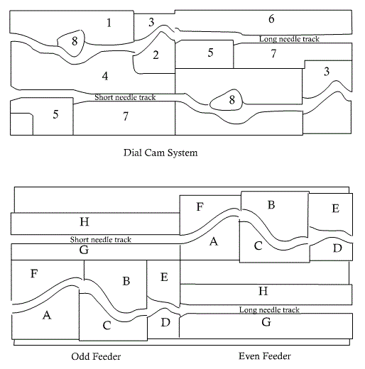
Interlock cam system:
In the figure the cylinder and dial camming to produce one course of ordinary interlock fabric which is actually work of two knitting feeders.
The cylinder cam:
A → clearing cam which lifts the needles to clear the old loop
B, C → stitch cam and guard cams respectively both vertically adjustable to control the stitch length.
D → up through to rise the needle whilst dial needle knock over
E, F → guard cam to complete the truck
G, H → guide cam to provide the track for idling needles
The dial system:
1. Raising cam for tuck position only
2, 3. Dial knock over cam
4. Guard cam to compete the truck
5. Auxiliary knock over cam to prevent the dial needle reentering the old loop
6, 7 Guide cams provides the tracks for idling needles
8. Sewing type clearing cam which may occupy the knitting position as shown in feeder 1 or in tuck position at feeder 2.
Machine parts:
The machine has two sets of needles on two different beds, one set on cylinder one in the dial bed. These two sets of needles must be exactly opposite to each other.
The machine has two separate cam system in each bed needles of different length called short needles and long needles. Each cam system controls half of the needles in alternate sequences. One cam system controls knitting at one feeder and other ca, system controls at the next feeders. T ale down mechanism is the same as the other Interlock and plain machines mechanism.
Interlock cam system:
In the figure the cylinder and dial camming to produce one course of ordinary interlock fabric which is actually work of two knitting feeders.
The cylinder cam:
A → clearing cam which lifts the needles to clear the old loop
B, C → stitch cam and guard cams respectively both vertically adjustable to control the stitch length.
D → up through to rise the needle whilst dial needle knock over
E, F → guard cam to complete the truck
G, H → guide cam to provide the track for idling needles
 |
| Cylinder Cam System |
1. Raising cam for tuck position only
2, 3. Dial knock over cam
4. Guard cam to compete the truck
5. Auxiliary knock over cam to prevent the dial needle reentering the old loop
6, 7 Guide cams provides the tracks for idling needles
8. Sewing type clearing cam which may occupy the knitting position as shown in feeder 1 or in tuck position at feeder 2.
Machine parts:
- Yarn career
- Break stop motion
- Yarn guides
- Dial
- Cylinder
- Dial cams
- Cylinder cams
- Dial needles
- Cylinder needles
- Oiling and air following devices
- Sensors
- Take up rollers
- Batch rollers
- Motor
- Belts
- Pulleys and gears Clutches
Knitting action:
Conclusion:
The circular Interlock machine is a very commonly used machine in country to make Interlock knitted fabric. So this experiment has significance in our study life. In this experiment we sketch the yarn path diagram of the machine, show the knitting action, cam system. We point out the various specification of the machine. So the experiment helps us to know more.
Above all the experiment is a successful one.


0 comments: